G-4 User’s Reference Guide
Encapsulation and Fragmentation
RFC 1490 describes an encapsulation method for carrying packets across a Frame Relay network. All protocol
packets are encapsulated within a Q.922 Annex A frame (a CCITT specification for data frames). The frames
must also contain information necessary to identify the protocol being carried, allowing the receiver to properly
process the incoming packets.
RFC 1490 also specifies a packet fragmentation and reassembly procedure for carrying frames over a Frame
Relay network which are larger than the network’s maximum frame size.
Note: RFC 1490 compliant devices from different vendors should interoperate with each other.
Network Protocol Addressing and Virtual Interfaces
Routing between LANs across a Frame Relay network is similar to routing across a point-to-point connection. A
PVC on one router is directly connected to a PVC on another router. The difference with Frame Relay is that
multiple PVCs can be supported on the same physical interface of a router.
Network protocol addresses are associated with each PVC using one of two methods: manual configuration or
auto-discovery (Netopia’s SmartMatch™).
Auto-discovery consists of two mechanisms: Inverse Address Resolution Protocol (InARP) and IP/IPX Routing
Information Protocol (RIP) requests.
InARP, as outlined in RFC 1293, allows dynamic mapping of protocol addresses to a DLCI. It can be used for
any network protocol, but is most commonly implemented for IP protocol.
When a router discovers a new, active PVC by communicating with the Frame Relay switch using the LMI
protocol, it uses InARP to discover the IP address of the remote router on the other end of the PVC, when the
PVC becomes active.
However, not all devices support InARP, so IP/IPX RIP is more common. The source address of the RIP
response packet gives the Netopia R3100 the other router’s address. In contrast, manual configuration
involves manually configuring the association between the PVC DLCI and network protocol addresses. However,
auto-discovery is the preferred configuration method because it is easier to set up than manual configuration.
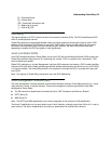
Frame Relay partial mesh support
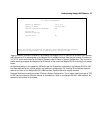
The following diagram depicts a partially meshed Frame Relay network:
router 1 router 2
router 3 router 4
2.0.0.1
4.0.0.1
3.0.0.1
5.0.0.1
1.0.0.1
1.0.0.3 1.0.0.4
1.0.0.2


