2-7
Features
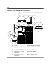
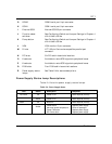
F DC power switch (convex
button)
Press to turn system DC power on or off.
G Reset switch (concave button) Press to cause a hard reset to the system;
the power-on self test (POST) will run.
H Power-on LED, green When green, power is present in system
(+5 and +12 VDC). When off, power is
turned off or power source is disrupted.
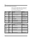
See Table 2-1 for a list and description of
the LED system status indicators.
I System alarm LED When green the system is OK. See Table
2-1 for a list and description of the LED
system status indicators.
J Drive activity LED When green, internal disk drives are
being accessed. See Table 2-1 for a list
and description of the LED system status
indicators.
K LCD panel Displays information about processor
type and system failures (error and
diagnostic information).
L SCSI drive status LEDs Left to right: Drive present/power on;
drive active; drive faulty. Each drive has
three LEDs visible above the bay from
the front. See Table 2-2 for a list of SCSI
disk drive status LED indicator
descriptions.


