


C. Configuration Options
3160-A2-GB21-90 February 2001
C-15
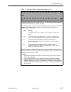
N1 N2 N3 N4 N5 N6 N7 N8 N9 N10 N11 N12 ... N24
Next
–
–
–
–
–
–
–
–
–
–
–
–
... Prev
OR
D1 D2 D3 D4 D5 D6 D7 D8 D9 D10 D11 D12 ... D24
Next
–
–
–
–
–
–
–
–
–
–
–
-- ... Prev
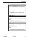
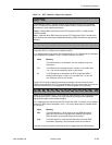
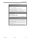
Data Port Channel Allocation (appears for the individual channel method only).
Designates the DS0 channel to allocate to this port, N1–N24 for the network interface and
D1-D24 for the DTE Drop/Insert (DSX-1) interface.
Line 1 displays the 24 channels for the network interface or the DTE Drop/Insert (DSX-1)
interface. Line 2 displays what is allocated to the DS0 channel indicated in Line 1.
Possible values for Line 2 are:
Select the channel by pressing the Function key under that number. To deallocate a port,
press the Function key under that port number. Pressing the Function key under channels
assigned to other ports has no effect.
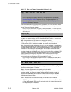
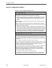
NOTES:
– The DSU/CSU automatically derives the data rate for the port from the number of
DS0 channels allocated.
– For the 3164 DSU/CSU there is a hardware limitation that limits the combined
bandwidth used by Port 1 and Port 3 to a total of 2048 kbps and the combined
bandwidth used by Port 2 and Port 4 to 2048 kbps. If a selection of Prt
n
causes this
limit to be exceeded, the selection is ignored and the “-” continues to be displayed
for the channel.
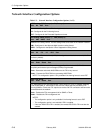
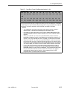
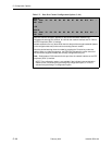
Table C-5. Data Port Channel Configuration Options (4 of 4)
Value Meaning
– This DS0 channel is not allocated. You can modify this value on this
screen.
Prt
n
This DS0 channel is allocated to port
n,
where
n
is a number from
1 to 4. You cannot modify this value on this screen for this port only.
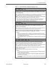
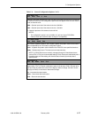
N
n
This DS0 channel is allocated to the network interface DS0
channel
n
, where
n
is a number from 1 to 24. You cannot modify this
value on this screen.
D
n
This DS0 channel is allocated to the DTE Drop/Insert (DSX-1)
interface DS0 channel
n
, where
n
is a number from 1 to 24. You can
modify this value on this screen.