


3. Operation
3160-A2-GB21-90 February 2001
3-5
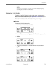
LEDs
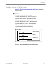
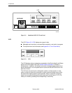
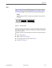
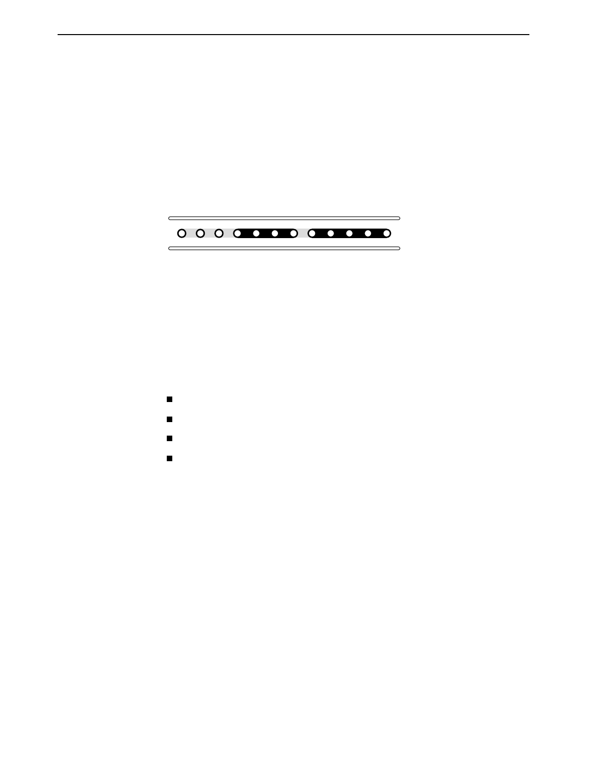
There are twelve LEDs on the DSU/CSU front panel. The five LEDs on the right
(Figure 3-5, DSU/CSU LEDs) are shared between the DTE Drop/Insert (DSX-1)
interface and the data ports. Refer to
Selecting the DTE Drop/Insert or Data Port
for LED Display
on page 3-12 to choose which port’s status the LEDs display.
NOTE:
The DTE Drop/Insert (DSX-1) interface is only available on 2-port and 4-port
DSU/CSUs.
Figure 3-5. DSU/CSU LEDs
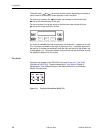
A green LED indicates normal operation. A yellow LED indicates a warning (for the
DTE Drop/Insert interface) or activity (for the data ports). Conditions are sampled
every tenth of a second.
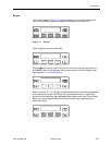
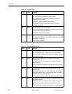
The twelve front panel LEDs are grouped into four sections to indicate the status of
the:
System LEDs (Table 3-1)
Network Interface LEDs (Table 3-2)
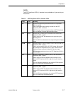
DTE Drop/Insert (DSX-1) Interface LEDs (Tabl e 3-3)
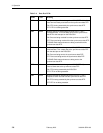
Data Port LEDs (Table 3 -4)
493-14301
OK
TEST SIG OOF ALRM
NETWORK TXD
EER SIG ALRM PDVOOF BPV
FAIL
DTR RXD CTS RTS