


1999 May 10 11
Philips Semiconductors Preliminary specification
Universal Serial Bus (USB) CODEC UDA1325
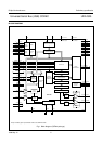
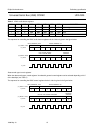
The clock source of the analog-to-digital interface
The clock source of the ADIF is the analog PLL or the ADC oscillator. The preferred clock source can be selected.
The ADC clock used for the ADC and decimation filters is obtained by dividing the clock signal coming from the analog
PLL or from the ADC oscillator by a factor Q.
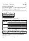
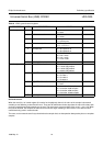
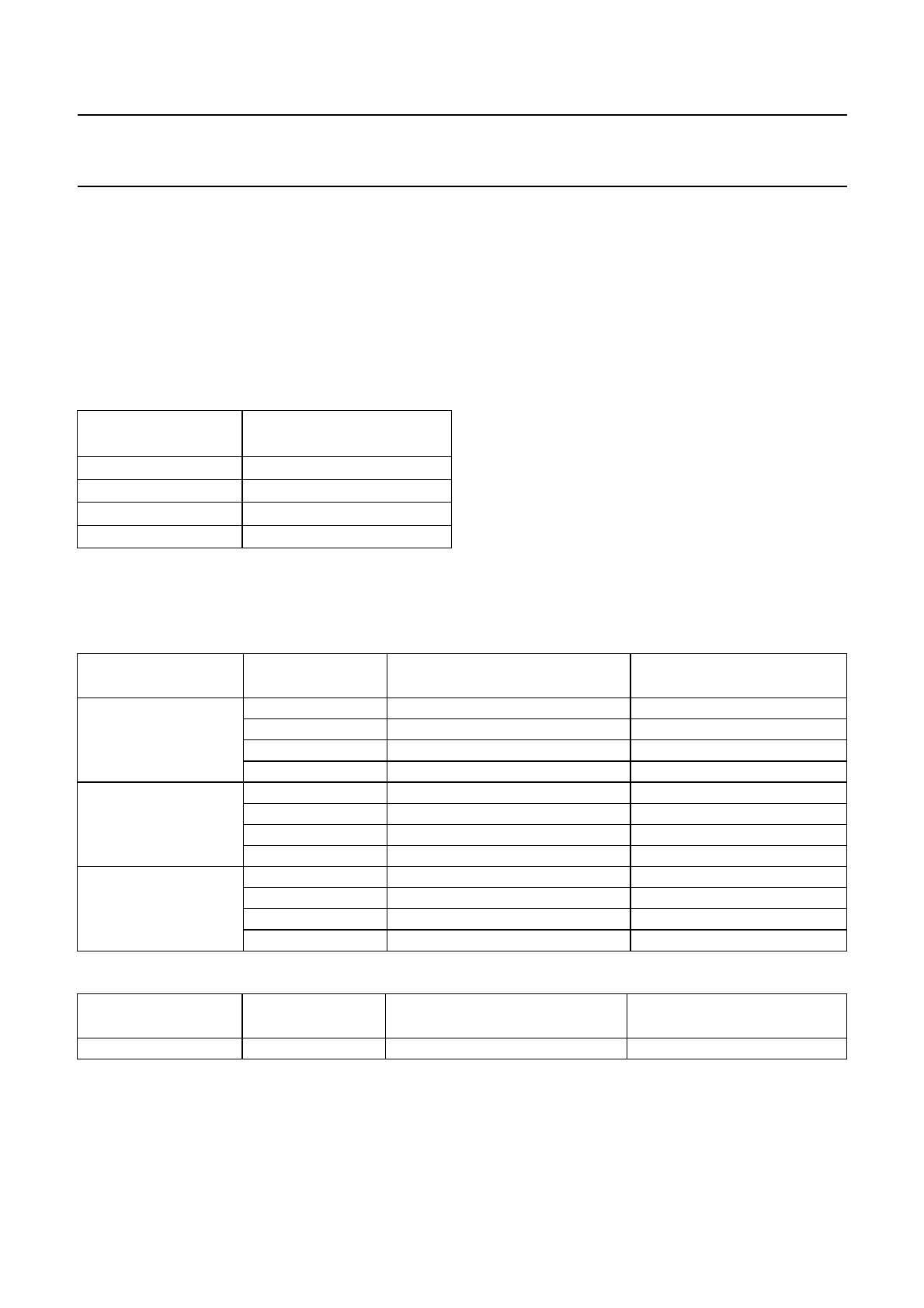
Using the analog PLL the user can select 3 basic APLL clock frequencies (see Table 1).
By connecting the appropriate crystal the user can choose any clock signal between 8.192 and 14.08 MHz via the ADC
oscillator.
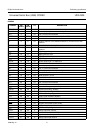
Table 1 The analog PLL clock output frequencies
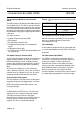
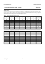
The dividing factor Q can be selected via the microcontroller. With this dividing factor Q the user can select a range of
ADC clock signals allowing several different sample frequencies (see Table 2).
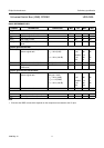
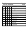
Table 2 ADC clock frequencies and sample frequencies based upon using the APLL as a clock source
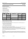
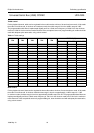
Table 3 ADC clock frequencies and sample frequencies based upon using the OSCAD as a clock source
Notes
1. The oscillator frequency (and therefore the crystal) of OSCAD must be between 8.192 and 14.08 MHz.
2. The Q factor can be 1, 2, 4 or 8.
3. Sample frequencies below 5 kHz and above 55 kHz are not supported.
FCODE (1 AND 0)
APLL CLOCK
FREQUENCY (MHz)
00 11.2896
01 8.1920
10 12.2880
11 11.2896
APLL CLOCK
FREQUENCY (MHz)
DIVIDE FACTOR Q ADC CLOCK FREQUENCY (MHz) SAMPLE FREQUENCY (kHz)
8.1920 1 4.096 32
2 2.048 16
4 1.024 8
8 0.512 (not supported) 4 (not supported)
11.2896 1 5.6448 44.1
2 2.8224 22.05
4 1.4112 11.025
8 0.7056 5.5125
12.2880 1 6.144 48
2 3.072 24
4 1.536 12
8 0.768 6
OSCAD CLOCK
FREQUENCY (MHz)
DIVIDE FACTOR Q ADC CLOCK FREQUENCY (MHz) SAMPLE FREQUENCY (kHz)
f
osc
(1)
Q
(2)
f
osc
/(2Q) f
osc
/(256Q)
(3)