


1999 May 10 27
Philips Semiconductors Preliminary specification
Universal Serial Bus (USB) CODEC UDA1325
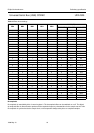
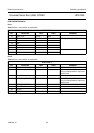
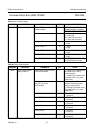
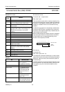
Table 21 I/O selection register
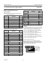
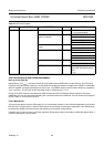
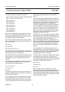
Table 22 Power control register
ADDRESS REGISTER COMMENTS BIT VALUE
1002h I/O selection register microcontroller control on
48 MHz oscillator
7 0 = UPC control disabled
(48 MHz oscillator is enabled)
1 = UPC control enabled
audio format 6 and 5 00 = 4-pins I
2
S
01 = 6-pins I
2
S
10 = 3-pins I
2
S (only input)
11 = 3-pins I
2
S (only input)
GP4 I/O if BIT0 = 1 4 0 = output
1 = input
GP3 I/O if BIT0 = 1 3 0 = output
1 = input
GP2 I/O if BIT0 = 1 2 0 = output
1 = input
GP1 I/O if BIT0 = 1 1 0 = output
1 = input
GP4 to GP1 function 0 0 = I
2
S usage
1 = general purpose usage
ADDRESS REGISTER COMMENTS BIT VALUE
1003h power control register
analog modules
suspend input selection for P3.1
of the microcontroller
7 0 = suspend from USB interface
connected to P3.1 during
normal operation
1 = suspend from restart circuit
connected to P3.1 (e.g. after
power-down)
interrupt input selection for
P3.3 (INT1_N) of the
microcontroller
6 0 = interrupt from USB
interface connected to P3.3
during normal operation
1 = interrupt from restart circuit
connected to P3.3 (e.g. after
power-down)
power APLL 5 0 = power on
1 = power off
power FSDAC 4 0 = power on
1 = power off
power ADC left 3 0 = power on
1 = power off
power ADC right 2 0 = power on
1 = power off
power PGA left 1 0 = power on
1 = power off
power PGA right 0 0 = power on
1 = power off