


1999 May 10 41
Philips Semiconductors Preliminary specification
Universal Serial Bus (USB) CODEC UDA1325
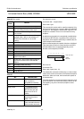
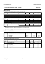
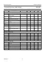
SDA and SCL lines for 100 kHz I
2
C devices
f
SCL
SCL clock frequency 0 − 100 kHz
t
BUF
bus free time between a STOP and
START condition
4.7 −−µs
t
HD;STA
hold time (repeated) START
condition
4.0 −−µs
t
LOW
LOW period of the SCL clock 4.7 −−µs
t
HIGH
HIGH period of the SCL clock 4.0 −−µs
t
SU;STA
set-up time for a repeated START
condition
4.7 −−µs
t
SU;STO
set-up time for STOP condition 4.0 −−µs
t
HD;DAT
data hold time 5.0 −−µs
t
SU;DAT
data set-up time 250 −−ns
t
r
rise time of both SDA and SCL
signals
−−1000 ns
t
f
fall time of both SDA and SCL
signals
−−300 ns
C
L(bus)
capacitive load for each bus line −−400 pF
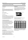
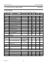
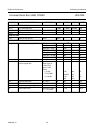
Oscillator 1 (system clock)
f
osc
oscillator frequency − 48 − MHz
δ duty factor − 50 − %
g
m
transconductance 12.8 22.1 30.2 mS
R
o
output resistance 0.6 1.1 2.3 kΩ
C
i(XTAL1a)
parasitic input capacitance XTAL1a 4.5 4.8 5.2 pF
C
i(XTAL2a)
parasitic input capacitance XTAL2a 4.1 4.6 5.0 pF
I
start
start-up current 3.7 7.6 13.0 mA
Oscillator 2 (for ADC clock)
f
osc
oscillator frequency 8.192 − 14.08 MHz
δ duty cycle − 50 − %
g
m
transconductance 8.1 13.6 18.1 mA/V
R
o
output resistance 1.3 2.0 4.0 kΩ
C
i(XTAL1b)
parasitic input capacitance XTAL1b 5.0 5.4 5.7 pF
C
i(XTAL2b)
parasitic input capacitance XTAL2b 4.1 4.6 5.0 pF
I
start
start-up current 2.4 5.0 8.4 mA
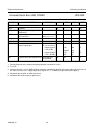
SYMBOL PARAMETER CONDITIONS MIN. TYP. MAX. UNIT