


1999 May 10 9
Philips Semiconductors Preliminary specification
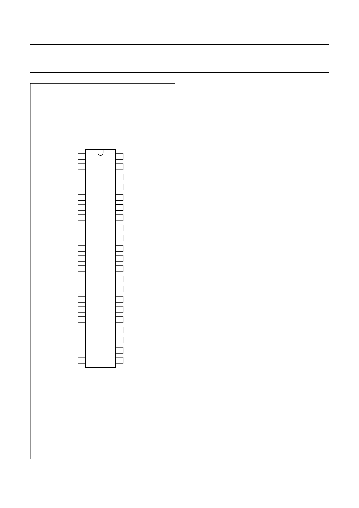
Universal Serial Bus (USB) CODEC UDA1325
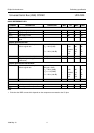
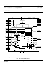
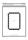
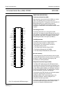
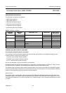
Fig.3 Pin configuration (SDIP42 package).
handbook, halfpage
UDA1325
MGM106
1
2
42
41
3
4
5
6
7
8
9
10
11
12
13
14
15
16
17
18
19
20
40
39
38
37
36
35
34
33
32
31
30
29
28
27
26
25
24
23
2221
V
SSA3
XTAL1a
XTAL2a
V
DDA3
VRP
VRN
VINR
V
SSA2
VINL
V
DDA2
V
ref(AD)
V
ref(DA)
V
SSA1
V
DDA1
VOUTR
RTCB
TC
VOUTL
V
SSO
V
DDO
V
DDX
DA
WS
BCK
GP2/DO
GP3/WSO
GP4/BCKO
SHTCB
D−
D+
V
DDI
V
SSI
V
SSE
V
DDE
GP1/DI
GP5/WSI
GP0/BCKI
SCL
SDA
V
SSX
XTAL1b
XTAL2b
FUNCTIONAL DESCRIPTION
The Universal Serial Bus (USB)
Data and power is transferred via the USB over a 4-wire
cable. The signalling occurs over two wires and
point-to-point segments. The signals on each segment are
differentially driven into a cable of 90 Ω intrinsic
impedance. The differential receiver features input
sensitivity of at least 200 mV and sufficient common mode
rejection.
The analog front-end
The analog front-end is an on-chip generic USB
transceiver. It is designed to allow voltage levels up to V
DD
from standard or programmable logic to interface with the
physical layer of the USB. It is capable of receiving and
transmitting serial data at full speed (12 Mbits/s).
The USB processor
The USB processor forms the interface between the
analog front-end, the ADIF, the ADAC and the
microcontroller. The USB processor consists of:
• A bit clock recovery circuit
• The Philips Serial Interface Engine (PSIE)
• The Memory Management Unit (MMU)
• The Audio Sample Redistribution (ASR) module.
Bit clock recovery
The bit clock recovery circuit recovers the clock from the
incoming USB data stream using four times over-sampling
principle. It is able to track jitter and frequency drift
specified by the USB specification.
Philips Serial Interface Engine (PSIE)
The Philips SIE implements the full USB protocol layer.
It translates the electrical USB signals into data bytes and
control signals. Depending upon the USB device address
and the USB endpoint address, the USB data is directed
to the correct endpoint buffer. The data transfer could be
of bulk, isochronous, control or interrupt type.
The functions of the PSIE include: synchronization pattern
recognition, parallel/serial conversion, bit
stuffing/de-stuffing, CRC checking/generation, PID
verification/generation, address recognition and
handshake evaluation/generation.
The amount of bytes/packet on all endpoints is limited by
the PSIE hardware to 8 bytes/packet, except for both
isochronous endpoints (336 bytes/packet).