


1999 May 10 35
Philips Semiconductors Preliminary specification
Universal Serial Bus (USB) CODEC UDA1325
VALIDATE BUFFER
Command: FAh.
Data: none.
When the microcontroller has written data into an IN buffer,
it should set the buffer full flag by the validate buffer
command. This indicates that the data in the buffer are
valid and can be sent to the host when the next IN token is
received.
General commands
READ CURRENT FRAME NUMBER
Command: F5h.
Data: read 1 or 2 bytes.
This command is followed by one or two data reads and
returns the frame number of the last successfully received
SOF. The frame number is eleven bits wide. The frame
number is returned least significant byte first. In case the
user is only interested in the lower 8 bits of the frame
number only the first byte needs to be read.
I
2
C MASTER/SLAVE INTERFACE
The I
2
C module implements a master/slave I
2
C-bus
interface with integrated shift register, shift timing
generation and slave address recognition. It is compliant
to the I
2
C-bus specification IC20/Jan92. I
2
C standard
mode (100 kHz SCL) and fast mode (400 kHz) are
supported. Low speed mode and extended 10 bit
addressing are unsupported.
Characteristics of the I
2
C-bus
The I
2
C-bus is for 2-way, 2-line communication between
different ICs or modules. The two lines are a serial data
line (SDA) and a Serial Clock Line (SCL). Both lines must
be connected to V
DDE
via a pull-up resistor.
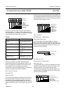
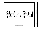
The timing definition of the I
2
C-bus is given in Fig.7.
Programmer’s view
For a detailed description of the I
2
C-bus protocol refer to
Philips Integrated Circuits Data Handbook IC20, 8XC552.
The programmer’s view of the I
2
C library function is -with
one exception- identical to that of the 8XC552
microcontroller. Only the bit rate frequency selection in
S1CON and the handling of the Timer 1 overflow
information deviates to accommodate 400 kHz operation.
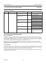
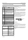
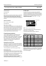
S1CON register
The CPU can read from and write to this 8-bit SFR.
Two bits are effected by the SIO1 hardware: the SI bit is
set when a serial interrupt is requested, and the STO bit is
cleared when a STOP condition is present on the I
2
C-bus.
The STO bit is also cleared when ENS1 = ‘0’. Reset
initializes S1CON to 00h.
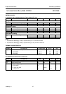
CR2, 1
AND 0-THE CLOCK RATE BITS
These three bits determine the serial clock frequency
when SIO1 is in a master mode.
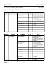
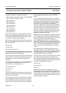
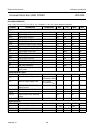
The various serial rates are shown in Table 28.
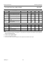
Table 28 Serial clock rates (SCL line)
When the CR bits are ‘111’, the maximum bit rate for the
data transfer will be derived from the Timer 1 overflow rate
divided by 2 (i.e. every time the Timer 1 overflows, the
SCL signal will toggle).
CR2 CR1 CR0
I
2
C BIT FREQUENCY
(kHz)
0 0 0 1200
0 0 1 600
0 1 0 400
0 1 1 300
1 0 0 150
1 0 1 100
110 75
1 1 1 3.9 ... 501
0 0 0 0 0 0 0 0
CR0
CR1
AA
SI
STO
STA
ENS1
CR2
76543210
Power On Value