


1999 May 10 12
Philips Semiconductors Preliminary specification
Universal Serial Bus (USB) CODEC UDA1325
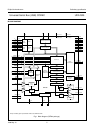
The Asynchronous Digital-to-Analog Converter
(ADAC)
The ADAC receives audio data from the USB processor or
from the digital I/O-bus. The ADAC is able to reconstruct
the sample clock from the rate at which the audio samples
arrive and handles the audio sound processing. After the
processing, the audio signal is upsampled, noise-shaped
and converted to analog output voltages capable of driving
a line output.
The ADAC consists of:
• A Sample Frequency Generator (SFG)
• FIFO registers
• An audio feature processing DSP
• Two digital upsampling filters and a variable hold
register
• A digital Noise Shaper (NS)
• A Filter Stream DAC (FSDAC) with integrated filter and
line output drivers.
The Sample Frequency Generator (SFG)
The SFG controls the timing signals for the asynchronous
digital-to-analog conversion. By means of a digital PLL,
the SFG automatically recovers the applied sampling
frequency and generates the accurate timing signals for
the audio feature processing DSP and the upsampling
filters.
The lock time of the digital PLL can be chosen (see
Table 8). While the digital PLL is not in lock, the ADAC is
muted. As soon as the digital PLL is in lock, the mute is
released as described in Section “Soft mute control”.
First-In First-Out (FIFO) registers
The FIFO registers are used to store the audio samples
temporarily coming from the USB processor or from the
digital I/O input. The use of a FIFO (in conjunction with the
SFG) is necessary to remove all jitter present on the
incoming audio signal.
The sound processing DSP
A DSP processes the sound features. The control and
mapping of the sound features is explained in Section
“Controlling the playback features of the ADAC”.
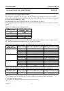
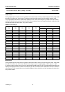
Depending on the sampling rate (f
s
) the DSP knows four
frequency domains in which the treble and bass are
regulated. The domain is chosen automatically.
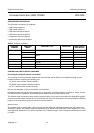
Table 4 Frequency domains for audio processing by the
DSP
The upsampling filters and variable hold function
After the audio feature processing DSP two upsampling
filters and a variable hold function increase the
oversampling rate to 128f
s
.
The noise shaper
A 3rd-order noise shaper converts the oversampled data
to a noise-shaped bitstream for the FSDAC. The in-band
quantization noise is shifted to frequencies well above the
audio band.
The Filter Stream DAC (FSDAC)
The FSDAC is a semi-digital reconstruction filter that
converts the 1-bit data stream of the noise shaper to an
analog output voltage. The filter coefficients are
implemented as current sources and are summed at
virtual ground of the output operational amplifier. In this
way very high signal-to-noise performance and low clock
jitter sensitivity is achieved. A post filter is not needed
because of the inherent filter function of the DAC.
On-board amplifiers convert the FSDAC output current to
an output voltage signal capable of driving a line output.
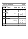
DOMAIN SAMPLE FREQUENCY (kHz)
1 5 to 12
212to25
325to40
440to55