


1999 May 10 34
Philips Semiconductors Preliminary specification
Universal Serial Bus (USB) CODEC UDA1325
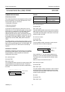
The data in the buffer are organized as follows:
Byte 0: transfer successful, number of data bytes (MSB)
Byte 1: number of data bytes (LSB)
Byte 2: data byte 0
Byte 3: data byte 1
Byte 4: data byte 2
Byte 5: data byte 3
Byte 6: data byte 4
Byte 7: data byte 5
Byte 8: data byte 6
Byte 9: data byte 7.
Bytes 0 and 1 indicate the number of bytes in the buffer.
Byte 0 is the Most Significant Byte (MSB). Byte 1 is the
Least Significant Byte (LSB). Only bits 1 and 0 of byte 0
are used in the number of bytes indication.
Bit 7 of byte 0 indicates if the transaction was successful
(bit 7 is ‘1’ if the transaction was successful). Bits 6 to 2 of
byte 0 are reserved.
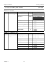
W
RITE BUFFER
Command: F0h.
Data: write n bytes (max. 10).
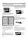
The write buffer command is followed by a number of data
writes, which load the endpoint buffer. After each write, the
internal buffer pointer is incremented by 1.
The buffer pointer is not reset to the buffer start by the write
buffer command. This means that writing a buffer can be
interrupted by any other command (except for select
endpoint).
The data must be organized in the same way as described
in the read buffer command. Bits 7 to 2 of byte 0 are
reserved and must be filled with zeros.
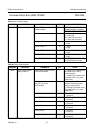
A
CKNOWLEDGE SETUP
Command: F1h.
Data: none.
The arrival of a SETUP packet flushes the IN buffer and
disables the validate buffer and clear buffer commands for
both IN and OUT endpoints.
The microcontroller needs to re-enable these commands
by the acknowledge setup command. This ensures that
the last SETUP packet stays in the buffer and no packet
can be sent back to the host until the microcontroller has
acknowledged explicitly that it has seen the SETUP
packet.
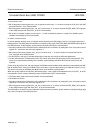
If the microcontroller is reading the data from a SETUP
packet, and a new SETUP packet arrives, the device must
accept this new SETUP packet. So the data, currently
being read by the microcontroller, is overwritten with the
new packet. On the arrival of the new packet, the
commands validate buffer and clear buffer are disabled.
If the microcontroller has finished reading the data from
the buffer, it will try to clear the buffer. The device will
ignore this command, so the new SETUP packet in the
buffer is not cleared. The microcontroller will now detect
the interrupt of the new SETUP packet and will start
reading the new data in the buffer.
A SETUP token can be followed by an IN token. After the
SETUP token, the microcontroller will start filling the IN
buffer. A SETUP token will clear the IN buffer. This avoids
the following problem: after a SETUP token, the
microcontroller fills the IN buffer. If the SETUP token is
followed by a SETUP token and shortly followed by an IN
token, the device will send the contents of the IN buffer to
the host. The IN buffer was filled after the first SETUP
token. That is why after a SETUP token the IN buffer is
cleared.
If the microcontroller is still filling the buffer when the
second SETUP token arrives, the SETUP token will clear
the IN buffer. If the microcontroller has filled the IN buffer,
it will validate the buffer. So clearing the IN buffer on
receiving a SETUP token is not enough.
If a SETUP token is received, the device will also disable
the validate buffer command for the IN buffer. If the
microcontroller needs to fill the buffer after a SETUP token,
the command acknowledge setup command must be sent
to enable the validate buffer command.
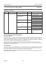
C
LEAR BUFFER
Command: F2h.
Data: none.
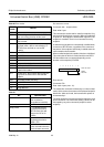
When a packet is received completely, an internal
endpoint buffer full flag is set. All subsequent packets will
be refused by returning a NACK to the host. When the
microcontroller has read the data, it should free the buffer
by the clear buffer command. When the buffer is cleared,
new packets will be accepted.