


1999 May 10 31
Philips Semiconductors Preliminary specification
Universal Serial Bus (USB) CODEC UDA1325
COMMAND DESCRIPTIONS
Command procedure
This chapter describes the commands that can be used by
the microcontroller to control the USB processor. There
are three basic types of commands:
• Initialization commands
• Data flow commands
• General commands.
A command is represented by an 8 bit code. It can be
followed by one or more data write cycles or one or more
read cycles or a combination. The PSIE_MMU_READY
output connected to Port 3.4 of the microcontroller
indicates that the previous action (command write, data
read or data write) has completed. A new action can only
be initiated if PSIE_MMU_READY is TRUE. The data is
valid from the moment PSIE_MMU_READY becomes
TRUE.
The PSIE contains a number of interrupt registers, one for
each endpoint. Every time a transition occurs, the interrupt
flag for the involved endpoint is set. The PSIE_MMU_INT
connected to Port 3.3 is an OR function of all interrupt
registers.
Initialization commands
Initialization commands are used during the enumeration
process of the USB network. They are used to set the USB
assigned address, enable endpoints and select the
configuration of the device.
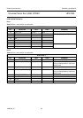
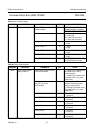
S
ET ADDRESS/ENABLE
Command: D0h.
Data: write 1 byte.
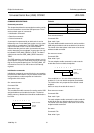
The set address/enable command is used to set the USB
assigned address and enable the function. The device
always powers up disabled and should be enabled after a
bus reset.
0
Address
Enable
01234567
000 0000
Power On Value
Table 24
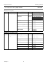
R
EAD ADDRESS/ENABLE
Command: D0h.
Data: read 1 byte.
The read address/enable command is used to read the
USB assigned address and the enable bit of the device.
The format of the data phase is the same as for the set
address/enable command.
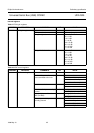
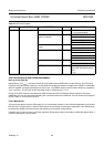
S
ET ENDPOINT ENABLE
Command: D8h.
Data: write 1 byte.
The set endpoint enable command is used to set the
enable bits for the non default endpoints.
If the enable bit is ‘1’, the non default endpoints are
enabled, if ‘0’, the non default endpoints are disabled.
The function then only responds to the default control
endpoint.
After bus reset, the enable bit is set to ‘0’.
R
EAD ENDPOINT ENABLE
Command: D8h.
Data: read 1 byte.
The read endpoint enable command is used to read the
enable bit for the non default endpoints of the function.
The format of the data phase is the same as for the set
endpoint enable command.
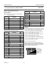
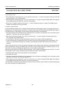
S
ET MODE
Command: F3h.
Data: write 1 byte.
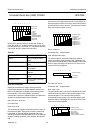
BIT DESCRIPTION
Address the value written becomes
the device address
Enable a ‘1’ enables this function
XXXXXXX0
Enable
Reserved
76543210
Power On Value