


1999 May 10 16
Philips Semiconductors Preliminary specification
Universal Serial Bus (USB) CODEC UDA1325
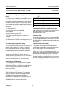
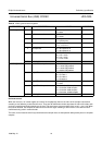
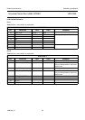
Table 8 ADAC general control registers
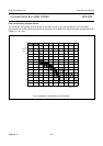
Soft mute control
When the mute (bit 1 of control register 0) is active for the playback channel, the value of the sample is decreased
smoothly to zero following a raised cosine curve. There are 32 coefficients used to step down the value of the data, each
one being used 32 times before stepping to the next. This amounts to a mute transition of 23 ms at f
s
= 44.1 kHz. When
the mute is released, the samples are returned to the full level again following a raised cosine curve with the same
coefficients being used in reversed order.
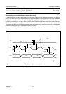
The mute, on the master channel is synchronized to the sample clock, so that operation always takes place on complete
samples.
REGISTER BIT DESCRIPTION VALUE COMMENT
Control register 0 0 reset ADAC 0 = not reset
1 = reset
1 soft mute control 0 = not muted
1 = mutes
2 synchronous/asynchronous 0 = asynchronous
1 = synchronous
select 0
3 channel manipulation 0 = L -> L, R -> R
1=L->R, R->L
4 de-emphasis 0 = de-emphasis off
1 = de-emphasis on
6 and 5 audio mode 00 = flat mode
01 = min. mode
10 = min. mode
11 = max. mode
7 selecting bit 0
Control register 1 1 and 0 serial I
2
S-bus input format 00 = I
2
S-bus
01 = 16-bit LSB justified
10 = 18-bit LSB justified
11 = 20-bit LSB justified
3 and 2 digital PLL mode 00 = adaptive
01 = fix state 1
10 = fix state 2
11 = fix state 3
select 00
4 digital PLL lock mode 0 = adaptive
1 = fixed
select 1
6 and 5 digital PLL lock speed 00 = lock after 512 samples
01 = lock after 2048 samples
10 = lock after 4096 samples
11 = lock after 16348 samples
select 00
7 selecting bit 1