


1999 May 10 15
Philips Semiconductors Preliminary specification
Universal Serial Bus (USB) CODEC UDA1325
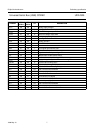
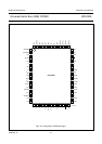
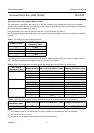
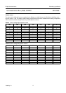
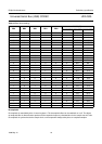
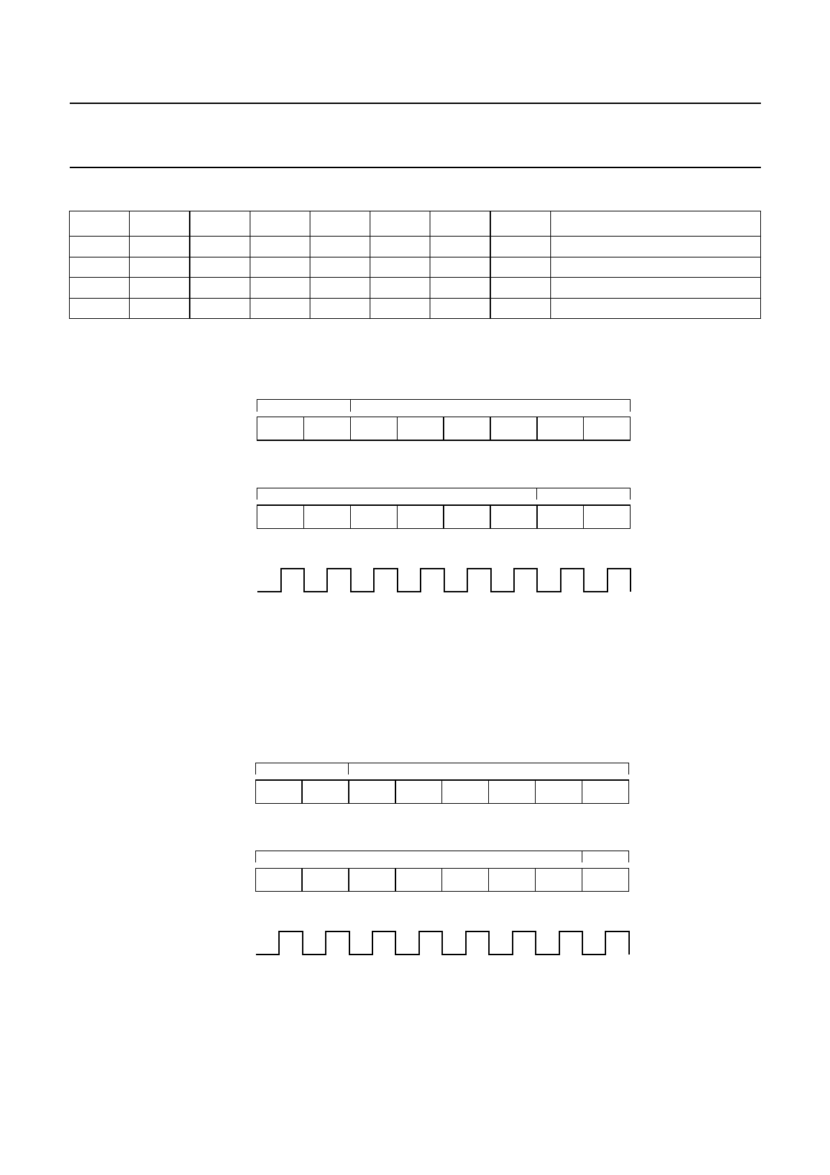
Table 7 ADAC audio feature registers
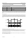
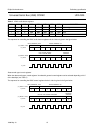
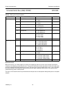
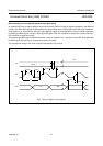
The sequence for controlling the ADAC audio feature registers via the L3-bus is given in the figure below.
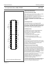
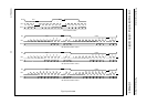
Data transfer type ‘control registers’
When the data transfer type ‘control registers’ is selected 2 general control registers can be selected depending on bit 7
of the data byte (see Table 7).
The sequence for controlling the ADAC control registers via the L3-bus is given in the figure below.
BIT7 BIT6 BIT5 BIT4 BIT3 BIT2 BIT1 BIT0 REGISTER
0 0 VR5 VR4 VR3 VR2 VR1 VR0 volume right
0 1 VL5 VL4 VL3 VL2 VL1 VL0 volume left
1 0 X BB4 BB3 BB2 BB1 BB0 bass
1 1 X TR4 TR3 TR2 TR1 TR0 treble
d
book, full pagewidth
MGS270
0
bit 0
DATA_TRANSFER_TYPE
L3_DATA
(L3_MODE = LOW)
0 1 0 1
DEVICE ADDRESS = $5
0 0 0
bit 7
X
bit 0
L3_DATA
(L3_MODE = HIGH)
X X X X
REGISTER
ADDRESS
LEFT VOLUME; TREBLE
RIGHT VOLUME; BASS
X
X X
bit 7
L3_CLK
d
book, full pagewidth
MGS269
0
bit 0
DATA_TRANSFER_TYPE
L3_DATA
(L3_MODE = LOW)
1 1 0 1
DEVICE ADDRESS = $5
0 0 0
bit 7
X
bit 0
L3_DATA
(L3_MODE = HIGH)
X X X X
REGISTER
ADDRESSDATA OF THE CONTROL REGISTER
X
X X
bit 7
L3_CLK