


1999 May 10 29
Philips Semiconductors Preliminary specification
Universal Serial Bus (USB) CODEC UDA1325
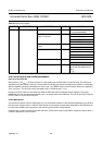
AT INITIALISATION TIME
• Bit 7of the power control register (mux_ctrl_suspend) must be set to ‘1’, in order to connect the CLK_ON of the USB
processor with P3.1 of the microcontroller
• Bit 6 of the power control register (mux_ctrl_int1) must be set to ‘0’, in order to connect the PSIE_MMU_INT output pin
of the USB processor with P3.3 (INT1_N) of the microcontroller
• Bit 7of the I/O selection register must be set to ‘1’, in order to enable the power-on control of the 48 MHz crystal
oscillator automatically by the microcontroller.
I
N NORMAL OPERATION MODE
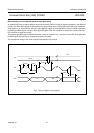
In normal operation working mode, a suspend can be initiated by the falling edge of the CLK_ON output signal of the
USB processor. This falling edge comes about 2 ms after the rising edge of the PSIE_MMU_SUSPEND output signal of
the USB processor. At this moment, several actions should be taken by the microcontroller:
• All analog modules of the UDA1325 must be switched off; this can be done by setting bits 5 to 0 of the power control
register to ‘1’ and bit 0 of the clock shop register to ‘1’
• Bit 6 of the power control register (mux_ctrl_int1) must be set to ‘1’, in order to awake from power-down by the
CLK_ON signal of the USB processor
• Put all GP pins in the high or low state (depending of how they are used in the UDA1325 application)
• Put the microcontroller in Power-down mode. This can be done via the PCON register of the microcontroller. This
results in an automatically switching off the 48 MHz crystal oscillator and with that all internal clocks (if they are
enabled).
On the rising edge of the CLK_ON output signal, the 48 MHz crystal oscillator will be switched on automatically and with
that all internal clocks (if they are enabled). At the same time, a counter starts counting for 2048 clock cycles (170 µs).
This time is necessary for stabilising the 48 MHz clock of the 48 MHz crystal oscillator.
When the counter reaches its end value (after 2048 cycles), a rising edge will be detected on the P3.3 (INT1_N) of the
microcontroller. At this moment, following actions should be taken by the microcontroller:
• The Power-down mode of the microcontroller must be switched off
• Re-initialise all GP pins
• All analog modules of the UDA1325 must be switched on; this can be done by setting bits 5 to 0 of the power control
register to ‘0’ and bit 0 of the clock shop register to ‘0’
• Bit 6 of the power control register (mux_ctrl_int1) must be set to ‘0’, in order to connect the PSIE_MMU_INT output pin
of the USB processor again with P3.3 (INT1_N) of the microcontroller.
The UDA1325 is now back in its normal operation mode and can be put back in power reduction mode by the falling edge
of the CLK_ON signal of the USB processor.