


1999 May 10 3
Philips Semiconductors Preliminary specification
Universal Serial Bus (USB) CODEC UDA1325
APPLICATIONS
• USB monitors
• USB speakers
• USB microphones
• USB headsets
• USB telephone/answering machines
• USB links in consumer audio devices.
GENERAL DESCRIPTION
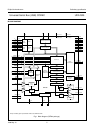
The UDA1325 is a single chip stereo USB codec
incorporating bitstream converters designed for
implementation in USB-compliant audio peripherals and
multimedia audio applications. It contains a USB interface,
an embedded microcontroller, an Analog-to-Digital
Interface (ADIF) and an Asynchronous Digital-to-Analog
Converter (ADAC).
The USB interface consists of an analog front-end and a
USB processor. The analog front-end transforms the
differential USB data into a digital data stream. The USB
processor buffers the incoming and outgoing data from the
analog front-end and handles all low-level USB protocols.
The USB processor selects the relevant data from the
universal serial bus, performs an extensive error detection
and separates control information and audio information.
The control information is made accessible to the
microcontroller. At playback, the audio information
becomes available at the digital I
2
S output of the digital I/O
module or is fed directly to the ADAC. At recording, the
audio information is delivered by the ADIF or by the digital
I
2
S input of the I
2
S-bus interface.
All I
2
S inputs and I
2
S outputs support standard I
2
S-bus
format and the LSB justified serial data format with word
lengths of 16, 18 and 20 bits.
Via the digital I/O module with its I
2
S input and output, an
external DSP can be used for adding extra sound
processing features for the audio playback channel.
The microcontroller is responsible for handling the
high-level USB protocols, translating the incoming control
requests and managing the user interface via general
purpose pins and an I
2
C-bus.
The ADAC enables the wide and continuous range of
playback sampling frequencies. By means of a Sample
Frequency Generator (SFG), the ADAC is able to
reconstruct the average sample frequency from the
incoming audio samples. The ADAC also performs the
playback sound processing. The ADAC consists of a
FIFO, an unique audio feature processing DSP, the SFG,
digital filters, a variable hold register, a Noise Shaper (NS)
and a Filter Stream DAC (FSDAC) with line output drivers.
The audio information is applied to the ADAC via the USB
processor or via the digital I
2
S input of the digital I/O
module.
The ADIF consists of an Programmable Gain Amplifier
(PGA), an Analog-to-Digital Converter (ADC) and a
Decimator Filter (DF). An Analog Phase Lock Loop (APLL)
or oscillator is used for creating the clock signal of the
ADIF. The clock frequency for the ADIF can be controlled
via the microcontroller. Several clock frequencies are
possible for sampling the analog input signal at different
sampling rates.
The wide dynamic range of the bitstream conversion
technique used in the UDA1325 for both the playback and
recording channel guarantees a high audio sound quality.
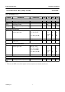
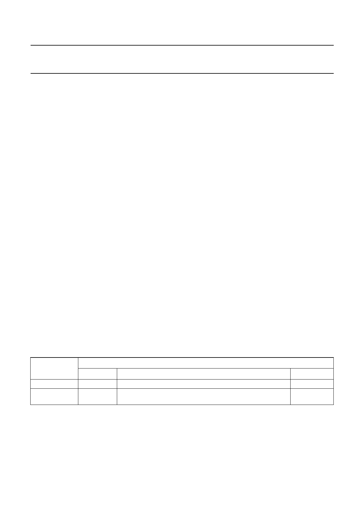
ORDERING INFORMATION
TYPE NUMBER
PACKAGE
NAME DESCRIPTION VERSION
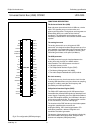
UDA1325PS SDIP42 plastic shrink dual in-line package; 42 leads (600 mil) SOT270-1
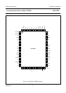
UDA1325H QFP64 plastic quad flat package; 64 leads (lead length 1.95 mm);
body 14 × 20 × 2.8 mm
SOT319-2