


1999 May 10 13
Philips Semiconductors Preliminary specification
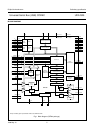
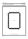
Universal Serial Bus (USB) CODEC UDA1325
USB ENDPOINT DESCRIPTION
The UDA1325 has following six endpoints:
• USB control endpoint 0
• USB control endpoint 1
• USB status interrupt endpoint 1
• USB status interrupt endpoint 2
• Isochronous data sink endpoint
• Isochronous data source endpoint.
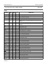
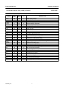
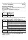
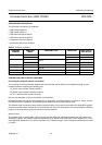
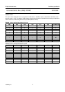
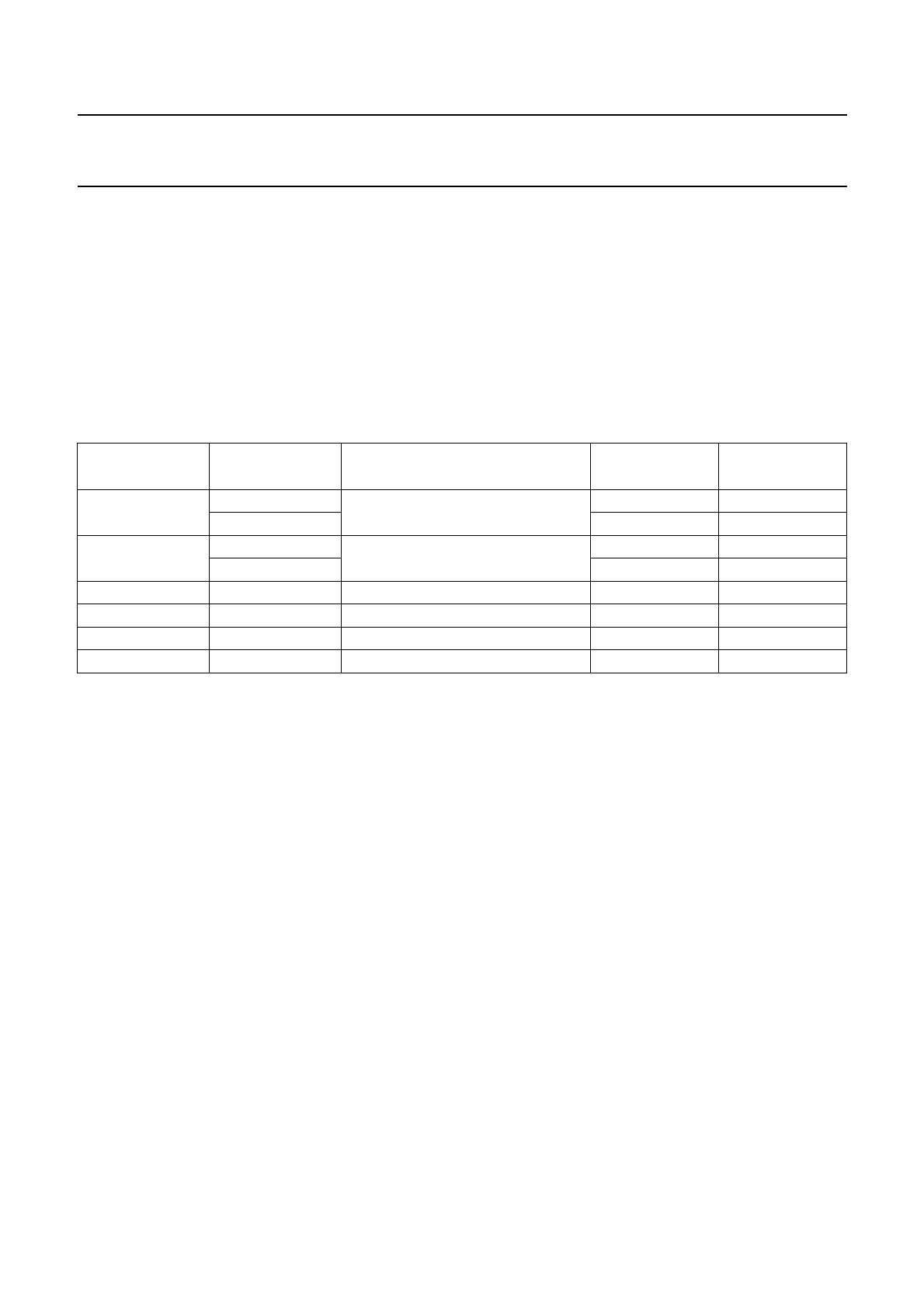
Table 5 Endpoint description
CONTROLLING THE PLAYBACK FEATURES
Controlling the playback features of the ADAC
The exchange of control information between the microcontroller and the ADAC is accomplished through a serial
hardware interface comprising the following pins:
L3_DATA: microcontroller interface data line
L3_MODE: microcontroller interface mode line
L3_CLK: microcontroller interface clock line.
See also the description of Port 3 of the 80C51 microcontroller.
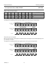
Information transfer through the microcontroller bus is organized in accordance with the so-called ‘L3’ format, in which
two different modes of operation can be distinguished; address mode and data transfer mode.
The address mode is required to select a device communicating via the L3-bus and to define the destination registers
for the data transfer mode. Data transfer for the UDA1325 can only be in one direction, from microcontroller to ADAC to
program its sound processing features and other functional features.
A
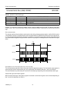
DDRESS MODE
The address mode is used to select a device (in this case the ADAC) for subsequent data transfer and to define the
destination registers. The address mode is characterized by L3_MODE being LOW and a burst of 8 pulses on L3_CLK,
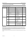
accompanied by 8 data bits on L3_DATA. Data bits 0 and 1 indicate the type of the subsequent data transfer as shown
in Table 6.
ENDPOINT
NUMBER
ENDPOINT
INDEX
ENDPOINT TYPE DIRECTION
MAX. PACKET
SIZE (BYTES)
0 0 control (default) out 8
1in8
1 2 control out 8
3in8
2 4 interrupt in 8
3 5 interrupt in 8
4 6 isochronous out out 336
5 7 isochronous in in 336