Chapter 4 Consumable Replacement
138
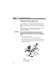
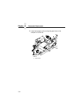
19. Using both hands, carefully slide the drum onto the drum
auxiliary rod. When the drum reaches the area where the
auxiliary rod connects to the drum shaft, lift the drum very
slightly over the connection. Then let the drum rest on the
rubber rollers as you gently guide it into the printer.
CAUTION
The drum must rest on the rubber rollers to avoid being
scratched.
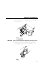
20. When the drum is fully inserted into the printer, the end of the
drum will be slightly recessed relative to the front of the printer.
At this point, the rubber guide rollers should be visible. Slightly
lift the drum up off of the rubber rollers and rotate the drum by
hand while applying inward pressure, until the drum moves
slightly farther into the printer and locks in place.
CAUTION
In order to position the drum slot and the drum shaft pin, push
the drum in all the way to the back and rotate it until you feel it
drop in place. Failure to lock the drum in place properly may
cause severe damage to the printer.
Never force the drum onto the shaft. If it feels as though the
drum is not seating properly, remove the drum and inspect the
shaft for any foreign material or burrs.
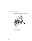
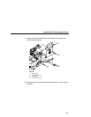
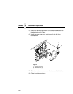
21. Remove the drum auxiliary rod from the drum shaft.
22. Install the nut and tighten it securely by hand on the drum shaft.
23. Install the lower inner cover and secure it with the two screws
removed earlier.
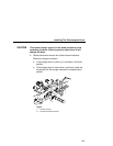
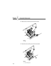
24. Install the drum plate and tighten the thumbscrews. While
installing the drum plate, place your thumb over the copper
grounding clip and hold it in place. Otherwise the grounding clip
can be bent, making no contact with the drum shaft.
25. After installing the drum plate, visually verify good electrical
contact between the copper grounding clip and the end of the
drum shaft.
Alternatively, measure the resistance. Connect one lead of an
ohmmeter to the bracket on the drum plate, and touch the other
lead to the edge of the drum. Normal resistance should be 0 Ω
.


