


Preliminary
Cabling
SANbox-16HA Fibre Channel Switch
Installer’s/User’s Manual 59005-03 Rev. A Multi-Chassis Fabrics 5-17
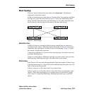
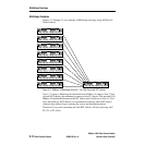
its user ports. In this case there is a T_Port for each user port. If a T_Port or CC
chassis fails, the chassis re-assigns the user port from the failed path to another
T_Port/CC that is good.
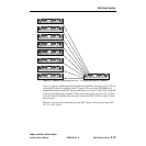
Note that any IO/T chassis can communicate with any other IO/T chassis with just
three chassis hops (counting the source and destination chassis).
There are eight user ports remaining on each IO/T chassis. All user ports may be F,
FL, SL, or TL_Ports.
Cabling
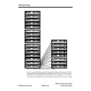
Any port on an IO/T chassis may be a T_Port. If you are using 2, 3, or 4 T_Ports on
each chassis, it is best to distribute these T_Ports as evenly as possible between the
ASIC port groups on each IO/T chassis. That is, don’t bunch the T_Ports up in one
ASIC port group. See “Tuning” on page 2-9 for more information about ASIC port
groups. Using a port as a T_Port does not affect any other port on the chassis.
Fiber Optic T_Port Connections
If you have individual connectors (one for each fiber), connect the transmit side of
the T_Port on one chassis to the receive side of the T_Port on the other chassis.
Connect the receive side of the T_Port on one chassis to the transmit side of the
T_Port on the other chassis. On the top row of ports on a chassis, the transmit
connector is the right-hand connector of each pair. On the bottom row of ports on a
chassis, the transmit connector is the left-hand connector of each pair. Refer to
Section 1 General Description for a drawing showing the transmit and receive
connectors in a port serviced by a fiber optic GBIC.
Keys on “Duplex” cable assemblies (a connector-pair containing both transmit and
receive together in one unit), prevent you from connecting them incorrectly.
Copper T_Port Connections
HSSDC and DB-9 connectors are duplex cable assemblies. That is, both the
transmit and receive contacts are part of the same keyed plug assembly. You can’t
plug them in wrong.
T_Port Cable Length
The maximum cable length between chassis depends on the type of interconnec-
tion media and its associated GBICs. Refer to Appendix A Reference Information
for the various types of interconnection media and GBICs.
Device Connections
Cable the user ports to their respective node devices. User ports are all those ports
on an IO/T chassis that are not used as T_Ports. User ports may be F, FL, SL, or
TL_Ports. Try to localize the traffic to each chassis as much as possible to
minimize the amount of traffic across the T_Port links between chassis.