


Preliminary
Front Panel Controls
SANbox-16HA Fibre Channel Switch
Installer’s/User’s Manual 59005-03 Rev. A General Description 1-19
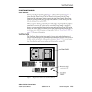
Front Panel Controls
Power Switches
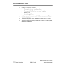
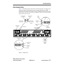
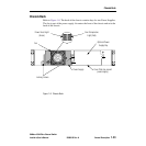
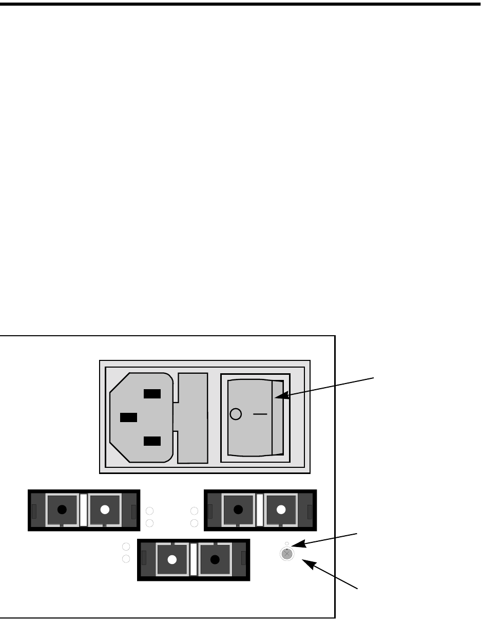
There are two Power Switches and Figure 1-5 shows their location. Figure 1-7
shows the right Power Switch. The left Power Switch controls the left Power
Supply and the right power Switch controls the right Power Supply. Each Power
switch is a rocker switch (press the right side (labeled 1) to turn it ON, press the
left side (labeled 0) to turn it OFF).
When you press a Power switch and turn it ON (and its associated Power Cable is
connected to an active AC outlet and its associated Power Supply is installed),
there is a two-second delay before the fans start and the Power Good LED on the
front of the chassis lights. The Power Good light indicates that the Switch logic is
receiving power within the proper voltage range. Refer to “Front Panel LEDs” on
page 1-20 for more information.
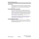
Test Mode Switch
The Test Mode Switch on the front panel is for use only under the direction of
QLogic Customer Support or your authorized maintenance provider. This switch is
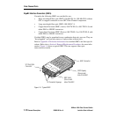
a rotary switch and must be in the position shown in Figure 1-7 for normal opera-
tion. Note that the small arrow on the end of the shaft is straight UP.
Figure 1-7 Right Power Switch and Test Mode Switch
14
16
15
Arrow
Arrow on shaft
must point UP.
Power Switch
Test Mode
Switch