


Preliminary
Major Switch Chassis Features
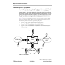
SANbox-16HA Fibre Channel Switch
1-10 General Description 59005-03 Rev. A Installer’s/User’s Manual
• Each chassis has two separate AC power inputs, one for each power supply.
The left AC power input provides input power to the left power supply. The
right AC power input provides input power to the right power supply.
• The Switch performs Power-On-Self-Tests (POSTs) each time it is powered-
up. POST provides one pass through the battery of tests, but does not test the
GigaBit Interface Converters (GBICs). The POST uses the Heartbeat LED to
indicate pass or fail test conditions. Refer to “Heartbeat LED (Yellow)” on
page 1-20 and“Power-On-Self-Test (POST)” on page 3-6.
• LEDs indicate the status of the Switch and each port. Refer to“Front Panel
LEDs” on page 1-20.
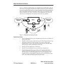
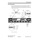
• The Switch contains an RJ-45 Ethernet connector that provides a manage-
ment connection to the outside world. The user can use a management station
connected via this network to manage the Switch. Refer to “Major Switch
Management Features” and “Switch Management Connector” later in this
section, and the Switch Management manual for more information.
• The Switch chassis may be connected to other Switch chassis to expand the
number of user ports. Refer to Section 5 Multi-Chassis Fabrics for more
information.
• The Switch chassis is shipped from the factory physically configured with
rubber feet on its bottom that allow it to sit on a flat surface and stack.
Mounting brackets (in a separate packet shipped with the Switch) allow you
to mount it in a 19-inch rack. When mounted in a rack, the Switch must be
supported by rails or a shelf. Refer to Section 2 Installation for the install
procedure and to Appendix A Reference Information for the dimensions and
type of rack.
• SANbox switch fabrics support the use of MKII switches as IO/T chassis in
mesh and Multistage™ topologies. Refer to “Three Multi-Chassis Topolo-
gies” on page 5-2 for more information about MKII compatibility.