


Preliminary
Place or Mount the Equipment
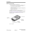
SANbox-16HA Fibre Channel Switch
2-2 Installation 59005-03 Rev. A Installer’s/User’s Manual
Place or Mount the Equipment
The Switch may be placed on a flat surface and stacked, or mounted in a 19” EIA
rack. The Switch comes with rubber feet on the bottom for placing it on a flat
surface.
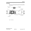
Air flow is front-to-back. The top of each chassis has dimples for the rubber feet of
a chassis stacked on top. Allow 163mm (6.5”) front, left side, and back.
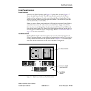
Shelf Mount
If you are not going to rack-mount the Switch, simply place it on a flat surface
being careful not to obstruct the air flow through the chassis.
Rack Mount
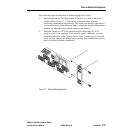
If you mount the Switch in a rack, you must install the rack-mounting brackets
supplied with the Switch. You may also need to remove the Switch’s rubber feet.
They are easily removable in case they are not compatible with your rack. Without
the rubber feet, the Switch occupies 2U of space in an EIA rack.
NOTE:
If this chassis is part of a Multistage Switch please read Section 5 Multi-Chassis
Fabrics. It may affect the way you place or mount this chassis.
NOTE: Rack Mounting Considerations
• The chassis must be installed on rails or on a shelf. The rack mounting brack-
ets cannot support the weight of the chassis.
• If the chassis is mounted in a closed or multi-unit rack assembly, the tempera-
ture of the chassis operating environment may be greater than the ambient
temperature of the room. Make sure that the operating temperature inside the
rack enclosure does not exceed the maximum rated ambient temperature as
defined in Appendix A Reference Information.
• Do not restrict the chassis airflow. Refer to Figure A-1 and Figure A-2 for
clearance information.
• Multiple rack-mounted units connected to the AC supply circuit may overload
that circuit or overload the AC supply wiring. Refer to the nameplate ratings
or Power Source loading in Appendix A Reference Information for clearance
information.
• Reliable grounding (earthing) in the rack must be maintained from the Switch
chassis to the AC power source. Please refer to the Danger notices on
page 2-5.