


Preliminary
AC Input Power Connectors and Fuses
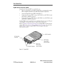
SANbox-16HA Fibre Channel Switch
1-22 General Description 59005-03 Rev. A Installer’s/User’s Manual
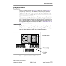
Traffic LED (Yellow)
Each port has its own Port Activity LED. The Port Activity LED for a particular
port is ON when Class 2, or 3 frames are entering or leaving the port. The Switch
turns the LED ON for 50 msec. for each frame, so you should be able to see it for
one frame. This LED will not light for frames following an arbitrated loop in
bypass mode.
AC Input Power Connectors and Fuses
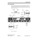
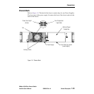
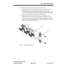
Refer to Figure 1-5. The chassis contains two Input Power Assemblies, one for
each power supply. The left assembly serves the left Power Supply. The right
assembly serves the right Power Supply. Each assembly contains a connector for a
standard 3-wire computer-type AC power cable (supplied with the Switch). The
power cable connects between an AC Input Power Connector and an AC outlet. For
purposes of redundancy, the AC outlets should be on separate circuits. Refer to
Appendix A Reference Information for the AC Power Requirements. See also
Section 2 Installation for installation procedures.
An Input Fuse Holder is incorporated into each AC Input Power Connector
assembly. they each hold two input fuses. Refer to Section 3 Diagnostics/Trouble-
shooting and to Section 4 Removal/Replacement Procedures. Refer also to
Appendix A Reference Information for fuse size.
Switch Management Connector
Refer to Figure 1-5. The Switch Management Connector is a 10/100BASE-T
Ethernet interface that provides a connection to a management station. Refer to the
Switch Management manual for information about how to connect the manage-
ment station and manage the Switch.