


Preliminary
Power-On-Self-Test (POST)
SANbox-16HA Fibre Channel Switch
Installer’s/User’s Manual 59005-03 Rev. A Diagnostics/Troubleshooting 3-9
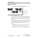
Flash Checksum Failure/Switch Management Port (Ethernet) Tests Good (3 Blinks)
The Switch is not operable The Flash checksum test verifies the integrity of the Flash
data. If the Flash data is corrupt, the POST next checks the Switch Management
port to find out if it is functional. It does this because the Switch Management port
is the load path for loading new Flash data. If the Switch Management port tests
good, the Switch blinks the Heartbeat LED three times between three-second
pauses. No port Logged-in LEDs blink. This means that you may load new Flash
control code via the Switch Management port. Refer to the Switch Management
manual for a description of how to load new Flash code.
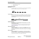
Flash Checksum Failure/ Switch Management port (Ethernet) Failure (4 Blinks)
The Switch is not operable. The Flash checksum test verifies the integrity of the Flash
data. If the Flash data is corrupt the POST next checks the Switch Management
port to find out if it is functional. It does this because the Switch Management port
is the load path for loading new Flash data. If the Switch Management port tests
bad, the Switch blinks the Heartbeat LED four times between three-second pauses.
No port Logged-in LEDs blink. This means that the Flash control code is corrupt
and the Switch Management port may not operate well enough to load new Flash
code.
Force PROM Mode in Effect (5 Blinks)
This is an alarm This indicates that the processor is reading the default configura-
tion from PROM instead of from Flash memory. This is due to the Test Mode
Switch being in the Force PROM position. You should never see this error in the
field if the Test mode switch is in the proper position. The Heartbeat LED will
blink five times between three-second pauses.
Switch ASIC Test Failure (6 Blinks)
The Switch is not operable. The Switch ASIC Test verifies the base functionality of
each Switch ASIC. This includes the control port interface and all functions that
can be performed within the confines of an individual ASIC. A failure indicates a
faulty Switch ASIC and blinks the Heartbeat LED six times between three-second
pauses. The Switch disables the ports associated with the bad ASIC and blinks
their Logged-in LEDs. An ASIC that fails this test could affect the operation of the
remaining ports.
GBIC Bypass Port Loopback Test Failure (7 Blinks)
The Switch is operable. The GBIC Bypass Port Loop-Back Test verifies (on a port-
by-port basis) the ability of each Switch ASIC to loop data out through the Serdes
chip on a port and back to the ASIC control port (bypassing the GBIC). A failure
indicates either a faulty Switch ASIC or an ASIC to Serdes interface problem and
blinks the Heartbeat LED seven times between three-second pauses. The Switch
disables the failing port or ports and blinks their Logged-in LEDs. The ports whose
Logged-in LEDs are not blinking have passed the test and are all usable.