


Preliminary
Major Switch Chassis Features
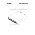
SANbox-16HA Fibre Channel Switch
Installer’s/User’s Manual 59005-03 Rev. A General Description 1-9
TL_Port Management
Refer to the Switch Management manual for more information. SANsurfer Switch
management provides the following:
• The user may choose which ports (if any) are TL_Ports.
• The user may use Name Server Zoning or Hard Zoning to limit the number
of Public devices that have access to a particular TL_Port to 31 devices or
less.
• The user may disable the Auto Learning feature for any TL_Port. The default
for each TL_Port is Auto Learning enabled.
• The user may manage the translation entries list for any TL_Port connected
to Private initiators. That is, the user may identify all off-loop targets for the
initiators on the particular TL_Port. Auto learning should be disabled for
these TL_Ports.
• SANsurfer provides a map of all AL_PAs on a Translated Loop. This
viewable map includes information about which AL_PA addresses are being
used by the TL_Port.
• SANsurfer provides a way to flag error conditions to the user.
• All switch management configuration information is stored in non-volatile
memory.
• The user may clear the stored configuration information.
Major Switch Chassis Features
The following is an overview of the major features of the Switch chassis:
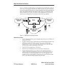
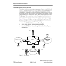
• A chassis can be defined as one of three stage types: Input/Output Transfer
(IO/T), Cross Connect (CC), or SL Private Loop. An IO/T chassis supports
all port types (F, FL, SL, TL, and T). A CC chassis supports only T_Ports as it
serves as a bridge between many IO/T chassis. An SL Private Loop chassis
supports SL_Ports and T_Ports. Refer to“Three Multi-Chassis Topologies”
on page 5-2 for more information about IO/T and CC stage types. Refer to
“SL Private Loop Stage Type” on page 1-5 for more information about the
SL Private Loop Stage Type.
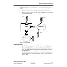
• You have the option to add a second power supply for total power supply
redundancy. When there are two power supplies, they each become “hot
pluggable”. Refer to “Power Supply(s)” on page 1-24 and also to Section 4
Removal/Replacement Procedures.