


Preliminary
Front Panel LEDs
SANbox-16HA Fibre Channel Switch
1-20 General Description 59005-03 Rev. A Installer’s/User’s Manual
Front Panel LEDs
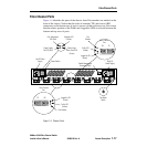
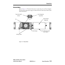
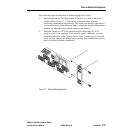
Refer to Figure 1-5. LEDs visible through lenses in the front of the chassis indicate
chassis and port status. During a Reset operation (for about two seconds at the
beginning of power-up) all LEDs are forced ON. The following definitions are
valid following the Power-On-Self-Test (POST) when the POST finds no errors.
Refer to Section 3 Diagnostics/Troubleshooting, for information about how the
LEDs act if the POST finds an error or if the control code (located in Flash
memory) hangs up.
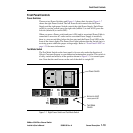
Heartbeat LED (Yellow)
The Heartbeat LED indicates the status of the internal Switch processor and the
results of Power-On-Self-Tests (POSTs) run at power-up.
Following a normal power-up the Heartbeat LED blinks about once per second to
indicate that the Switch passed the POSTs and the internal Switch processor is
running.
Refer to Section 3 Diagnostics/Troubleshooting, for more information about
Heartbeat LED error codes.
Switch Logic Power Good LED (Green)
This LED is ON when any Power Supply is delivering power within normal limits
to the Switch logic (the Power Button must also be depressed). If you have redun-
dant power supplies, the Power Good LED will stay ON even when one power
supply stops working and the other picks up the load. The LED will go OFF when
no supply is delivering the proper logic voltages.
Power Supply Fail LED (RED)
This LED is normally OFF. It comes ON only when one supply in a redundant
configuration fails, but the other supply has picked up the load. When this LED is
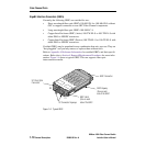
ON, it is a signal to look at the Power Supply LEDs on the back of each Power
Supply to determine which supply failed. Refer to Figure 1-5 for the location of the
power supplies and their LEDs. This LED is not meaningful in a system with only
one Power Supply.