


Preliminary
Cable Fibre Channel Devices to the Switch
SANbox-16HA Fibre Channel Switch
2-12 Installation 59005-03 Rev. A Installer’s/User’s Manual
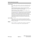
Fiber Optic Connections
Keys on “Duplex” cable assemblies (a connector-pair containing both transmit and
receive fastened together in one unit), prevent you from connecting them incor-
rectly.
On the Switch end of the connection, on the top row of ports, the transmit
connector is the right-hand connector of each pair. On the bottom row of ports, the
transmit connector is the left-hand connector of each pair.
On the device end, you will have to consult the appropriate adapter or device
manual to determine the connector orientation.
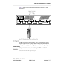
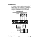
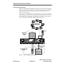
In some cases you may need to connect a loop of devices to the Switch without the
use of a Hub. Note in Figure 2-5 that these devices are connected in a loop from the
transmit side of a loop port on the Switch, through each device in the loop, then
back to the receive side of the original loop port on the Switch. Connect the
transmit connector on a loop port to the receive connector on the first device in the
loop. Continue to connect each device in the loop, transmit to receive. Then
connect the transmit connector on the last device in the loop to the receive
connector of the same loop port on the Switch that you connected to the first
device in the loop.
Copper Connections
HSSDC and DB-9 connectors are duplex cable assemblies. That is, both the
transmit and receive contacts are part of the same keyed plug assembly. You can’t
plug them in wrong. Connect one end of the cable to the Loop device and the other
end to a port on the Switch.
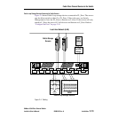
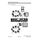
Examples
Figures 2-4 through 2-7 are examples of device connections to a single chassis
switch. The same concepts apply to fabrics containing multiple chassis.