


Preliminary
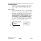
SANbox-16HA Fibre Channel Switch
viii
List of Figures and Tables 59005-03 Rev. A Installer’s/User’s Manual
List of Figures and Tables
Figure 1-1 SANbox-16HA Fibre Channel Switch 1-1
Figure 1-2 Segmented Loop Topology Example 1-4
Figure 1-3 SCSI Example 1-6
Figure 1-4 TCP/IP Example 1-7
Figure 1-5 Chassis Front 1-17
Figure 1-6 Typical GBIC 1-18
Figure 1-7 Right Power Switch and Test Mode Switch 1-19
Figure 1-8 Chassis Back 1-23
Figure 2-1 Cabinet Mounting Bracket 2-3
Figure 2-2 IEC Class 1 Laser Information Label 2-4
Figure 2-3 Extending Buffer Credits by Chaining Ports 2-11
Figure 2-4 Cabling 2-13
Figure 2-5 Variety of Public Connections 2-14
Figure 2-6 Private Segmented Loop Connections 2-15
Figure 2-7 Private Translated Loop Connections 2-16
Figure 3-3 Test Mode Switch 3-6
Figure 4-1 Fuse Holder Removal 4-1
Figure 4-2 Fuse Replacement 4-2
Figure 4-3 Removing GBICs that have individually operated latches 4-3
Figure 4-4 Removing GBICs that have bail-operated latches 4-4
Figure 4-5 Replacing GBICs 4-4
Figure 4-6 Power Supply Removal 4-6
Figure 5-1 Cascade Example 5-5
Figure 5-2 Mesh Example 5-9
Figure 5-3 SANbox-16 Multistage with one T_Port link from each IO/T chassis 5-14
Figure 5-4 SANbox-16 Multistage with two T_Port links from each IO/T chassis 5-15
Figure 5-5 SANbox-16 Multistage with eight CC chassis 5-16
Figure A-1 SANbox-16HA Switch Front/Back Dimensions in Millimeters (Inches) A-9
Figure A-2 SANbox-16HA Switch Top View Dimensions in Millimeters (Inches) A-10
Table 3-1 Troubleshooting Matrix (Dual Power Supply) 3-2
Table 3-2 Troubleshooting Matrix (Single Power Supply) 3-4