


Preliminary
Fibre Channel Ports
SANbox-16HA Fibre Channel Switch
Installer’s/User’s Manual 59005-03 Rev. A General Description 1-17
Fibre Channel Ports
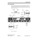
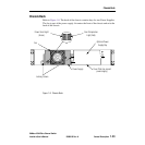
Figure 1-5 identifies the parts of the chassis front. Port numbers are marked on the
front of the chassis. Notice that the order of transmit (TX) and receive (RX)
connectors on the bottom row of ports is reverse of that on the top row. Also notice
that the relative position of the Traffic and Logged-In LEDs is reversed between the
bottom and top rows of ports.
Figure 1-5 Chassis Front
24
6
8
10
12
14
16
1
3
5
7
9
11
13
15
Rx
Tx
RxTx
5
8
Heartbeat LED
(Yellow)
Power Supply
Fail LED (Red)
Over Temperature
LED (Red)
Power Good LED
(Green)
Left AC Power
Supply
Right AC
Power Supply
Power Switch
Switch Management
Connector (RJ45)
Port
Number
RX
TX
Traffic LED
(Yellow)
Logged-In LED
(Green)
Fibre Channel
Port
Port Number
Traffic LED
(Yellow)
Logged-In LED
(Green)
RX
TX
Fibre Channel
Port
Test Mode
Switch
Switch Logic