


Introduction Quatech SDS User’s Manual
Identifying parts
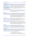
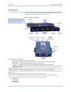
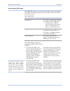
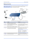
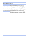
Figure 1 shows the connectors and indicator lights (LEDs) of the SDS.
See below for a description of each item shown.
Figure 1 – Connectors and Indicators
The actual number and
location of serial ports will
vary according to the model.
Power LED
Data LEDs
Power
j
ack
Speed LED
Ethernet jack
Link LED
Serial ports
Reset button Status LED
Speed LED
Link LED
Power jack
Status LED
Reset button
Ethernet jack
Power LED
Data LEDs
The SDS has several indicator LEDs:
¾ Power (blue) – indicates when the SDS has line power
¾ Data (red/green) – indicates serial port data activity by blinking red for RS-232 or green for RS-422/485
¾ Status (green) – indicates when the embedded processor is up and running
¾ Link (green) – indicates when a network link has been established; located in the Ethernet connector
¾ Speed (amber) – differentiates between 100Base-T (glowing) and 10Base-T (off) Ethernet connection speeds; located in
the Ethernet connector
The DB-9 serial port(s) connect to your serial device(s) and can support RS-232, RS-422, or RS-485 connections. They are
located either to the left, to either side of the Ethernet port, or on the front panel, depending on the model.
The RJ-45 Ethernet jack connects the SDS
t
o the Internet or to your Intranet. It has two small status LEDs: Link (green) and
Speed (amber).
The power jack should be connected to a +5V power source, as provided with the SDS.
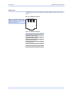
The Reset button puts the SDS through a reset cycle and can also restore the SDS to the factory default settings.
The information label (not shown) is on the bottom of the SDS. It includes the following:
¾ MAC address
¾ Serial number
¾ Certifications
¾ Pinout diagram
Serial ports
Page 8 940-0183-153 July 2005