


Introduction Quatech SDS User’s Manual
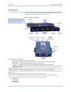
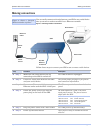
Locating serial and network ports
Serial port(s)
SDS serial ports connect via cables to your serial device(s). The
number of these ports will vary depending on the SDS model. All SDS
models come with DB-9 serial port connectors. RS-232 “M” models
include adapter plugs to convert the DB-9 connectors to RJ-45
connectors. See
Making connections on page 13 for directions on
connecting an SDS serial port to a serial device.
Note: The location of the serial
port(s) varies, depending on
the model.
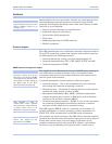
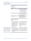
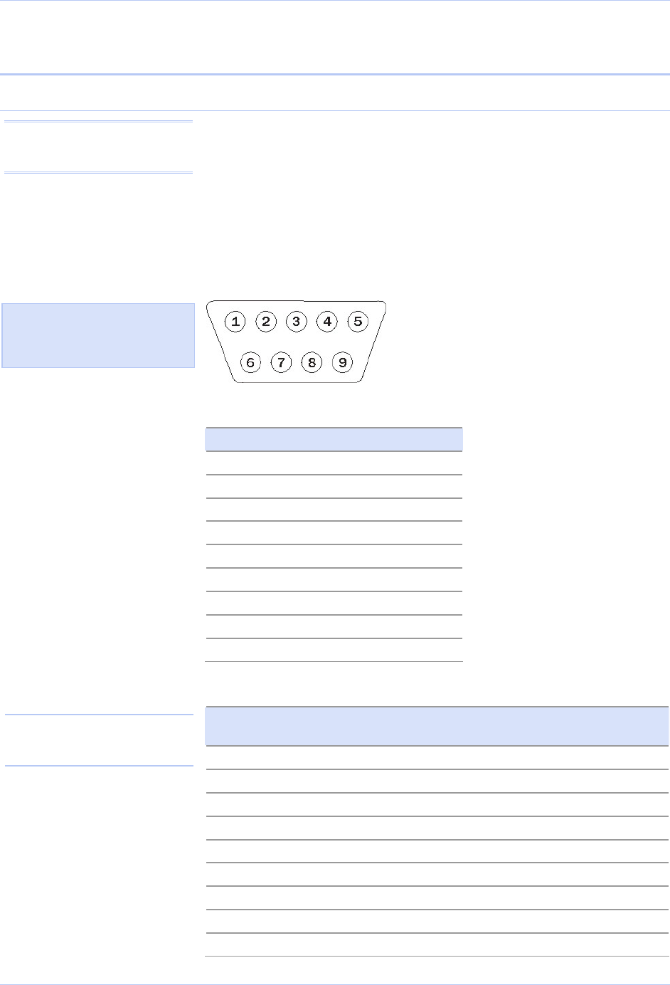
The following figures and tables show the serial port pinouts for RS-
232 and RS-232/422/485 applications.
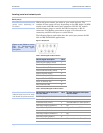
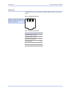
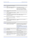
Figure 2 - DB-9 pinouts
Table 3 - RS-232 signals on DB-9 connector
RS-232 signal description DB-9
Data Carrier Detect (DCD) 1
Receive Data (RxD) 2
Transmit Data (TxD) 3
Data Terminal Ready (DTR) 4
Signal Ground (GND) 5
Data Set Ready (DSR) 6
Request To Send (RTS) 7
Clear To Send (CTS) 8
Ring Indicator (RI) 9
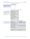
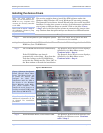
Table 4 - RS-422/485 signals on DB-9 connector
RS-422/485 signal description
four-wire mode
DB-9 RS-422/485 signal description
two-wire mode
Auxiliary Input (AuxIn–) 1 NC
Receive Data (RxD+) 2 NC
Transmit Data (TxD+) 3 Transmit/Receive Data (Data+)
Auxiliary Output (AuxOut–) 4 NC
Signal Ground (GND) 5 Signal Ground (GND)
Receive Data (RxD–) 6
NC
Auxiliary Output (AuxOut+) 7
NC
Auxiliary Input (AuxIn+) 8
NC
Transmit Data (TxD–) 9 Transmit/Receive Data (Data–)
Note: Pins labeled NC are
indeterminate in two-wire mode
and should be left unconnected.
Figure 3 and Tables 3 and 4
show the RS-232/422/485
DB-9 pinouts and signal
descriptions.
Page 10 940-0183-153 July 2005