


Quatech SDS User’s Manual Introduction
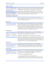
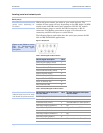
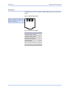
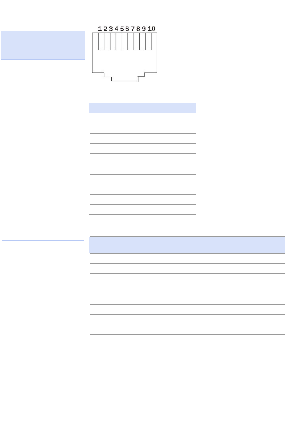
Figure 3 - RJ-45 pinouts (DB-9 to RJ-45 adapter)
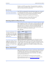
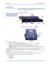
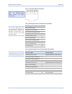
Figure 4 and Tables 5 and 6
show the RS-232/422/485
-RJ-45 pinouts and signal
descriptions.
Table 5 - RS-232 signals on RJ-45 connector (DB-9 to RJ-45 adapter)
RS-232 signal description RJ-45
Ring Indicator (RI) 1
Request To Send (RTS) 2
Data Terminal Ready (DTR) 3
Signal Ground (GND) 4
Transmit Data (TxD) 5
Receive Data (RxD) 6
Data Carrier Detect (DCD) 7
Data Set Ready (DSR) 8
Clear To Send (CTS) 9
No Connection 10
Note: If your serial port cable
uses an 8-pin RJ-45 plug, you
can use the center eight pins of
the SDS’ RJ-45 connector for
RS-232 communications. You
will lose access to the Ring
Indicator signal.
Table 6 - RS-422/485 signals on RJ-45 connector (DB-9 to RJ-45 adapter)
RS-422/485 signal description
four-wire mode
RJ-45 RS-422/485 signal description
two-wire mode
Transmit Data (TxD–) 1 Transmit/Receive Data (Data–)
Auxiliary Output (AuxOut+) 2
NC
Auxiliary Output (AuxOut–) 3
NC
Signal Ground (GND) 4 Signal Ground (GND)
Transmit Data (TxD+) 5 Transmit/Receive Data (Data+)
Receive Data (RxD+) 6
NC
Auxiliary Input (AuxIn–) 7
NC
Receive Data (RxD–) 8
NC
Auxiliary Input (AuxIn+) 9
NC
No Connection 10 No Connection
Note: Pins labeled NC are
indeterminate in two-wire mode
and should be left unconnected.
July 2005 940-0183-153 Page 11