


Quatech SDS User’s Manual Configuring the SDS using a Web interface
Step Procedure Description
performance for most applications.
Low Latency mode heavily favors
responsiveness over throughput.
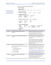
Step 3c Set the Heart Beat Time to a value from 1
to 65534 seconds. Default is 45 seconds.
Note: Use a value of 0 to disable the heartbeat
timer.
Heartbeat messages help detect when a
connection has been lost between the PC
driver and the SDS.
If you need quick notification that the
connection has been lost, set this timer to
a shorter value.
If you are more concerned about network
traffic, set this timer to a longer value.
Step 3d Set the Baud Rate. The SDS and the serial device(s) to
which it is attached must use the same
serial connection speed.
Step 3e Set the Parity. Parity can be odd, even, or none.
Step 3f Set the Data Bits. Data Bits can be 7 or 8.
Step 3g Set the Stop Bits. Stop Bits can be 1 or 2.
Step Procedure Description
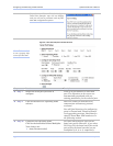
Step 3h Set the Flow Control. Flow control determines the handshake
method used between the SDS and the
serial device(s) to stop the serial
input/output process
Step 3i Click on the desired Auto TCP Mode
selector.
Your choices are:
¾ DSR – Initiate the TCP connection
when the SDS serial port’s DSR
becomes active
¾ Data – Initiate the TCP connection
when the SDS serial port receives data
This selection determines whether the
SDS port will initiate a communications
link when DSR becomes active or when
data is received at the serial port.
Typically, the DTR output of the device
to which you are connecting drives the
DSR input on the SDS serial port.
Step 3j Set the Auto TCP timeout interval if you
selected Data as the Auto TCP Mode.
Note: This selection is only available if the
Auto TCP Mode selector is set to Data.
Otherwise, it is grayed out.
Sets the amount of time before the TCP
connection is dropped after data stops.
Step 3k Set the IP Address of the TCP host to
which the SDS will connect.
This selection sets the IP address to be
used in Auto TCP mode.
Step 3l Set the TCP Port number of the TCP host
to which the SDS will connect.
This selection sets the TCP port for Auto
TCP modes.
Steps 4a through 4d apply only to RS-232/422/485 (MEI) units
Step 4a Configure the serial port interface. This series of steps only applies to MEI
July 2005 940-0183-153 Page 67