APPLICATION
2.3 Timers
2-35
4513/4514 Group User’s Manual
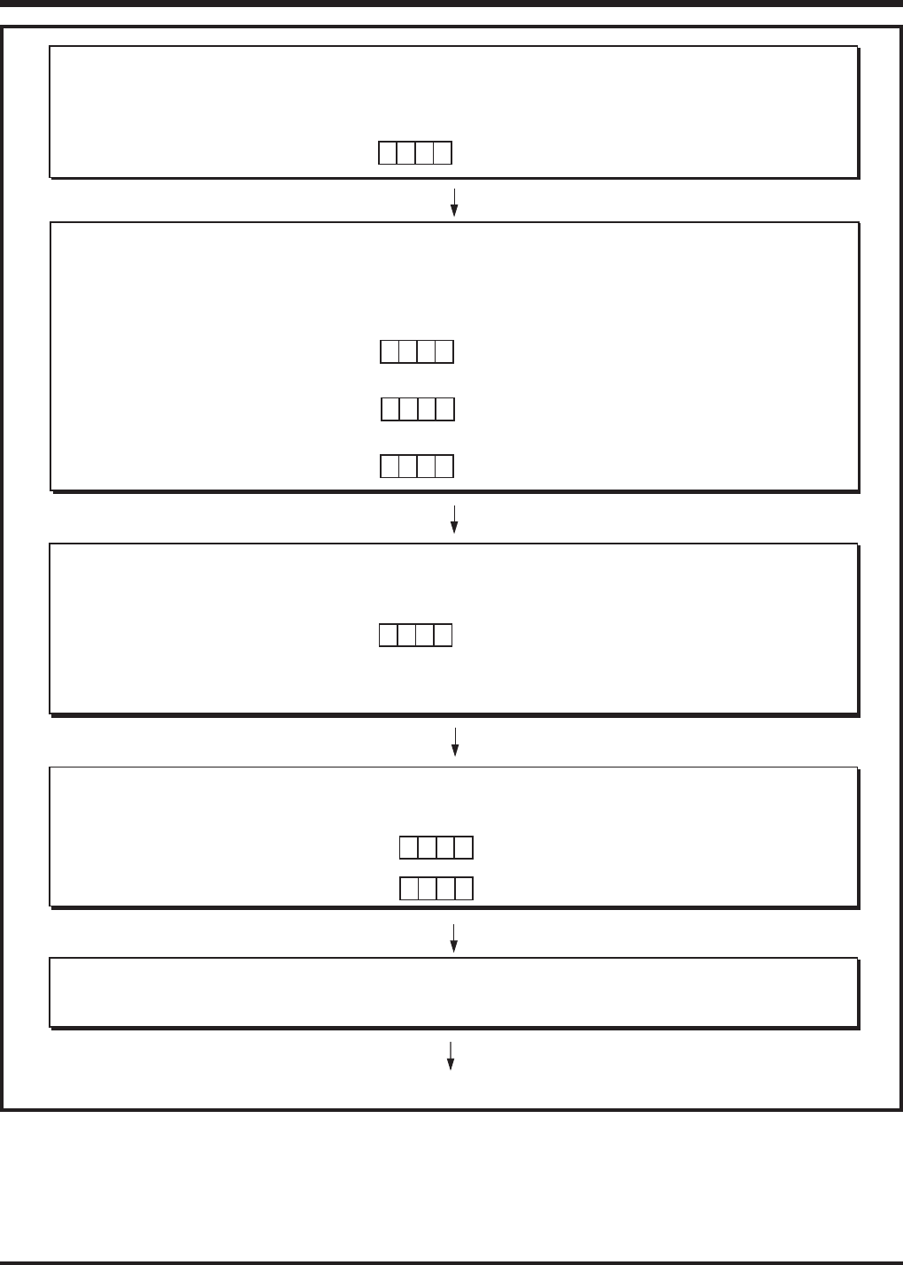
Fig. 2.3.6 CNTR0 output control setting example
b3 b0
➀ Disable Interrupts
Timer 3 and timer 4 interrupt are temporarily disabled.
Interrupt enable flag INTE
Interrupt control register V2
“0”
✕✕
All interrupts disabled (DI instruction)
Timer 3 and timer 4 interrupt occurrence disabled
(TV2A instruction)
0
0
b3 b0
10
➁ Stop Timer Operation
Timer is temporarily stopped.
Dividing ratio of prescaler is selected.
Timer 3 count source is selected.
Timer 4 count source is selected.
Timer control register W3
✕
Timer 3 stop (TW3A instruction)
Prescaler selected for count source
Timer 4 stop (TW4A instruction)
Timer 3 underflow selected for count source
Instruction clock divided by 4 selected
(TW1A instruction)
b3 b0
01
0
Timer control register W4
✕
✕
Timer control register W1
b3 b0
00
0
✕
➂ Set Timer Value, Select CNTR1 Output
CNTR1 output is selected.
Timer 3 and timer 4 count time are set.
Timer control register W6
Timer 3 reload register R3
Timer 3 reload register R4
“2916”
“FF16”
Timer count value 41 set (T3AB instruction)
Timer count value 255 set (T4AB instruction)
b3 b0
1
✕
1
✕
CNTR1 output selected (TW6A instruction)
➃ Start Timer Operation
Timer 3 and timer 4 temporarily stopped are restarted.
Timer 3 operation start (TW3A instruction)
Timer 4 operation start (TW4A instruction)
b3 b0
10
Timer control register W3
Timer control register W4
✕
1
b3 b0
10
✕
0
➄ Enable Interrupts
Interrupt enable flag INTE
“1”
All interrupts enabled (EI instruction)
“✕”: it can be “0” or “1.”


