1-16
HARDWARE
4513/4514 Group User’s Manual
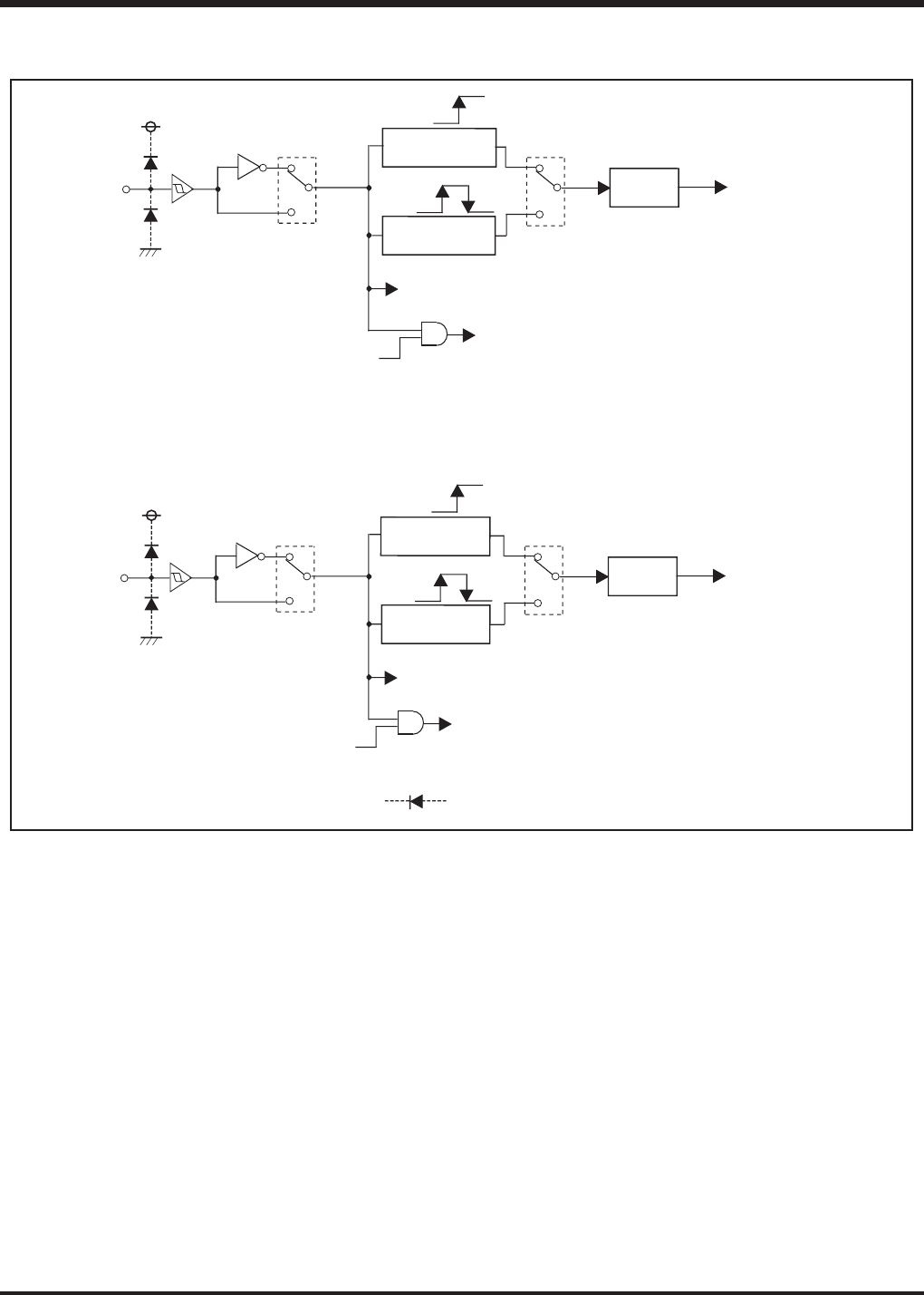
External interrupt circuit structure
PIN DESCRIPTION
0
1
I2
2
0
1
EXF1
I2
1
SNZI1
P3
1
/INT1
0
1
I1
2
Wakeup
Skip
0
1
EXF0
I1
1
SNZI0
P3
0
/INT0
Rising
Falling
One-sided edge
detection circuit
Both edges
detection circuit
External 0
interrupt
External 1
interrupt
Wakeup
Skip
Rising
Falling
One-sided edge
detection circuit
Both edges
detection circuit
This symbol represents a parasitic diode on the port.


