


M3062PT3-RPD-E User’s Manual 1. Outline
REJ10J0040-0600 Rev.6.00 July 01, 2006 Page 15 of 104
1.3 System Configuration
1.3.1 System Configuration
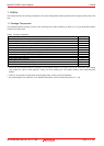
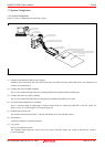
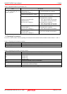
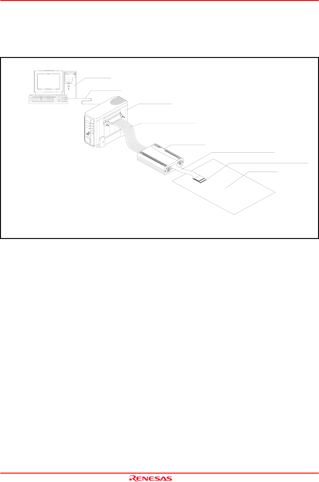
Figure 1.1 shows a configuration of the PC4701 system.
Figure 1.1 System configuration
(1) Emulation pod M3062PT3-RPD-E (this product)
Emulation pod for the M16C/60 Series M16C/62P Group and M16C/30 Series M16C/30P Group. This emulation pod
contains an evaluation MCU.
(2) Flexible cable FLX120-RPD (included)
This is a 120-conductor flexible cable for connecting the PC4701 emulator and the emulation pod.
(3) Flexible cable M3T-FLX160C (included)
This is a 160-conductor flexible cable for connecting the emulation pod and the user system.
(4) Converter board M30800T-PTC (included)
This is a converter board for connecting to 100-pin 0.65mm pitch LCC socket IC61-1004-051 on the user system. For
details, refer to "2.8 Connecting the User System" (page 30).
(5) Emulator main unit PC4701
The emulator main unit for the M16C, 7700 and 740 families to be used with this product.
(6) Host machine
A personal computer to control the emulator.
(7) User system
This is your application system.
This emulator cannot supply the power to the user system. Therefore design your system so that the user system is
powered separately.
Interface cable
(1) Emulation pod
(2)
Flexible cable connecting PC4701
(3) Flexible cable connecting user system
(4)
Package converter board for connecting user system
Host machine
(7) User system
(5) Emulator main unit
(6 ) Host machine