


M3062PT3-RPD-E User’s Manual Contents
REJ10J0040-0600 Rev.6.00 July 01, 2006 Page 9 of 104
Contents
Page
Preface.........................................................................................................................................................................
3
Releated Manuals........................................................................................................................................................ 3
Important......................................................................................................................................................................
4
Precautions for Safety .................................................................................................................................................
6
Contents.......................................................................................................................................................................
9
User Registration .......................................................................................................................................................
11
Terminology................................................................................................................................................................
12
1. Outline....................................................................................................................................................................
13
1.1 Package Components ..................................................................................................................................
13
1.2 Other Tool Products Required for Development...........................................................................................
14
1.3 System Configuration ...................................................................................................................................
15
1.3.1 System Configuration...........................................................................................................................
15
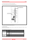
1.3.2 Names and Functions of the PC4701 Front Panel LEDs ....................................................................
16
1.4 Specifications................................................................................................................................................
18
1.5 Operating Environment.................................................................................................................................
19
2. Setup......................................................................................................................................................................
20
2.1 Flowchart of Starting Up the Emulator..........................................................................................................
20
2.2 Installing the Emulator Debugger (M16C PC4701 Emulator Debugger)......................................................
21
2.2.1 Installing the Emulator Debugger ........................................................................................................
21
2.3 Connecting the Host Machine ......................................................................................................................
22
2.4 Connecting the PC4701 ...............................................................................................................................
23
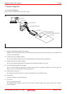
2.4.1 Connecting the FLX120-RPD to the PC4701 ......................................................................................
23
2.4.2 Connecting the FLX120-RPD to the Emulation Pod............................................................................
24
2.5 Turning ON the Power ..................................................................................................................................
25
2.5.1 Checking the Connections of the Emulator System ............................................................................
25
2.5.2 Turning ON/OFF the Power .................................................................................................................
25
2.5.3 LED Display When the Emulator Starts Up Normally ..........................................................................
26
2.6 Downloading Firmware.................................................................................................................................
27
2.6.1 When It is Necessary to Download Firmware......................................................................................
27
2.6.2 Downloading Firmware in Maintenance Mode.....................................................................................
27
2.7 Self-check.....................................................................................................................................................
28
2.7.1 Self-check Procedure...........................................................................................................................
28
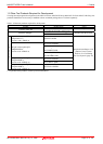
2.7.2 If an Error is Detected in the Self-check ..............................................................................................
29
2.8 Connecting the User System........................................................................................................................
30
2.8.1 Connecting to a 80-pin 0.65mm Pitch Foot Pattern.............................................................................
31
2.8.2 Connecting to a 100-pin LCC socket...................................................................................................
32
2.8.3 Connecting to a 100-pin 0.65mm Pitch Foot Pattern (Part 1)..............................................................
33
2.8.4 Connecting to a 100-pin 0.65mm Pitch Foot Pattern (Part 2)..............................................................
34
2.8.5 Connecting to a 100-pin 0.65mm Pitch Foot Pattern (Part 3)..............................................................
35
2.8.6 Connecting to a 100-pin 0.5mm Pitch Foot Pattern (Part 1)................................................................
36
2.8.7 Connecting to a 100-pin 0.5mm Pitch Foot Pattern (Part 2)................................................................
37
2.8.8 Connecting to a 128-pin 0.5mm Pitch Foot Pattern.............................................................................
38
2.9 Changing Settings ........................................................................................................................................
39
2.9.1 Removing/Attaching the Upper Cover .................................................................................................
39
2.9.2 Each Setting.........................................................................................................................................
40
2.9.3 Selecting Clock Supply ........................................................................................................................
41
2.9.4 Switch Settings ....................................................................................................................................
45
2.9.5 Jumper Switches JP1 and JP2 on the M30620T3-PRT (MCU-dependent board 1) ...........................
47
2.9.6 Installing and Removing Network Resistors for Pullup........................................................................
48
2.9.7 Bypass Capacitors for A/D Converter ..................................................................................................
49