


M3062PT3-RPD-E User’s Manual 2. Setup
REJ10J0040-0600 Rev.6.00 July 01, 2006 Page 44 of 104
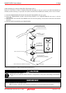
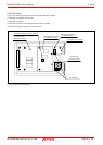
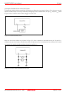
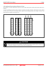
(5) Using the Oscillator Circuit on the User System
To operate this product with an external clock, construct the oscillator circuit as shown in Figure 2.22 in the user system and
input the oscillator output at 50% duty (within the operating range of the evaluation MCU) into pin X
IN
. And pin X
OUT
should
be open. Choose "External" in the emulator debugger to use this clock.
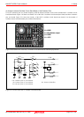
Figure 2.22 External oscillator circuit
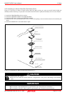
Make note that in the oscillator circuit shown in Figure 2.23 where a resonator is connected between pins X
IN
and X
OUT
,
oscillation does not occur because a flexible cable, buffer IC and other devices are used between the evaluation MCU and the
user system. It is same for sub-clock oscillator circuits (X
CIN
and X
COUT
).
Figure 2.23 Circuit in which oscillation does not occur