


M3062PT3-RPD-E User’s Manual 2. Setup
REJ10J0040-0600 Rev.6.00 July 01, 2006 Page 34 of 104
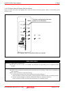
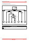
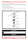
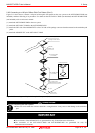
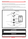
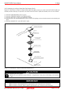
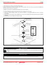
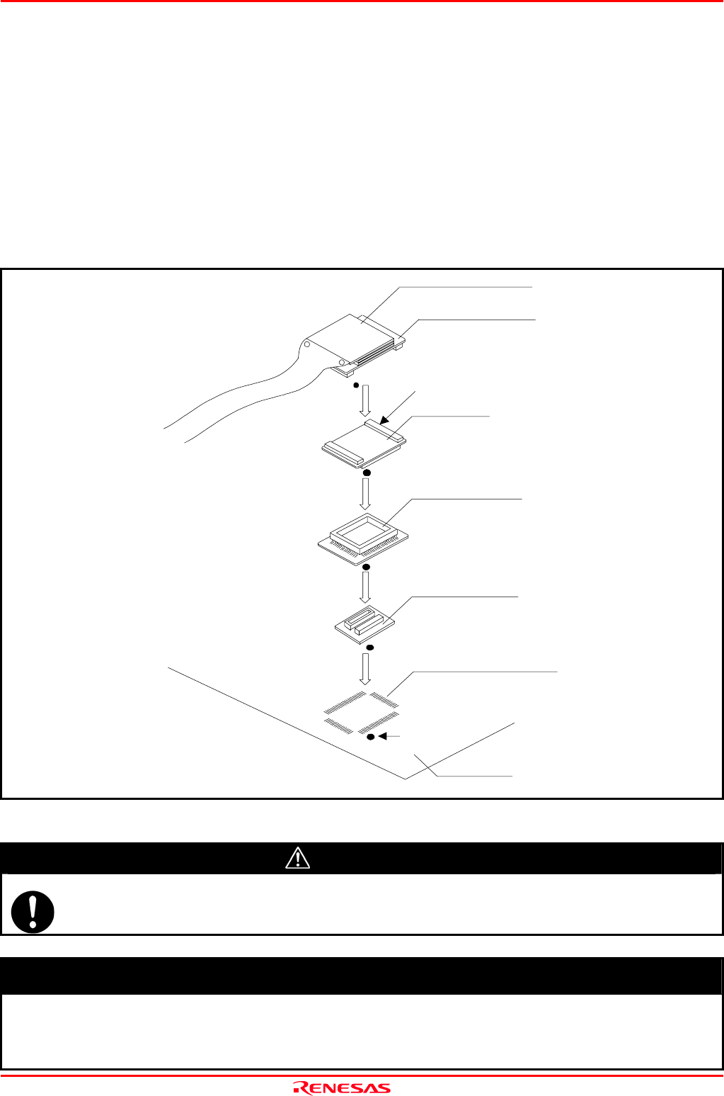
2.8.4 Connecting to a 100-pin 0.65mm Pitch Foot Pattern (Part 2)
Figure 2.12 shows how to connect a 100-pin 0.65mm pitch foot pattern on the user system to the M3T-DIRECT100S (not
included), and here following is its procedure. For details on the M3T-100LCC-DMS (not included) and M3T-DIRECT100S
(not included), refer to each user's manual.
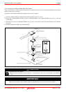
(1) Attach the M3T-DIRECT100S to the user system.
(2) Attach the M3T-100LCC-DMS to the M3T-DIRECT100S.
(3) Attach the CN2 side of the M30800T-PTC to the CN2 side of the package converter board connected to the emulation pod
probe.
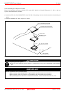
(4) Attach the M30800T-PTC to the M3T-100LCC-DMS.
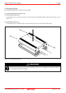
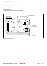
Figure 2.12 Connecting to a 100-pin 0.65mm pitch foot pattern (2/3)
CAUTION
Note on Connecting the User System:
z Take care not to attach the converter board in a wrong direction. It may cause a fatal damage to the emulation
pod.
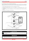
IMPORTANT
Notes on Connectors of the Converter board:
z The connectors of the M30800T-PTC are guaranteed for only 50 insertion/removal iterations.
z The connectors of the M3T-100LCC-DMS and M3T-DIRECT100S are guaranteed for only 20
insertion/removal iterations.
M3T-100LCC-DMS
(not included)
CN2 side
(3)
(4)
M30800T-PTC
(2)
(1)
100-pin 0.65mm pitch
(PRQP0100JB-A) foot pattern
No. 1 pin
User system
M3T-DIRECT100S
(not included)
Package converter board
Tip of emulation pod probe