


M3062PT3-RPD-E User’s Manual 1. Outline
REJ10J0040-0600 Rev.6.00 July 01, 2006 Page 17 of 104
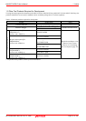
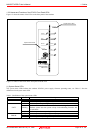
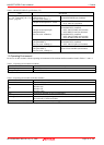
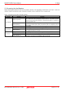
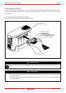
(2) Target Status LEDs
The target status LEDs indicate the target MCU's operating status and target board's power supply. Table 1.4 lists the definition
of each target status LED.
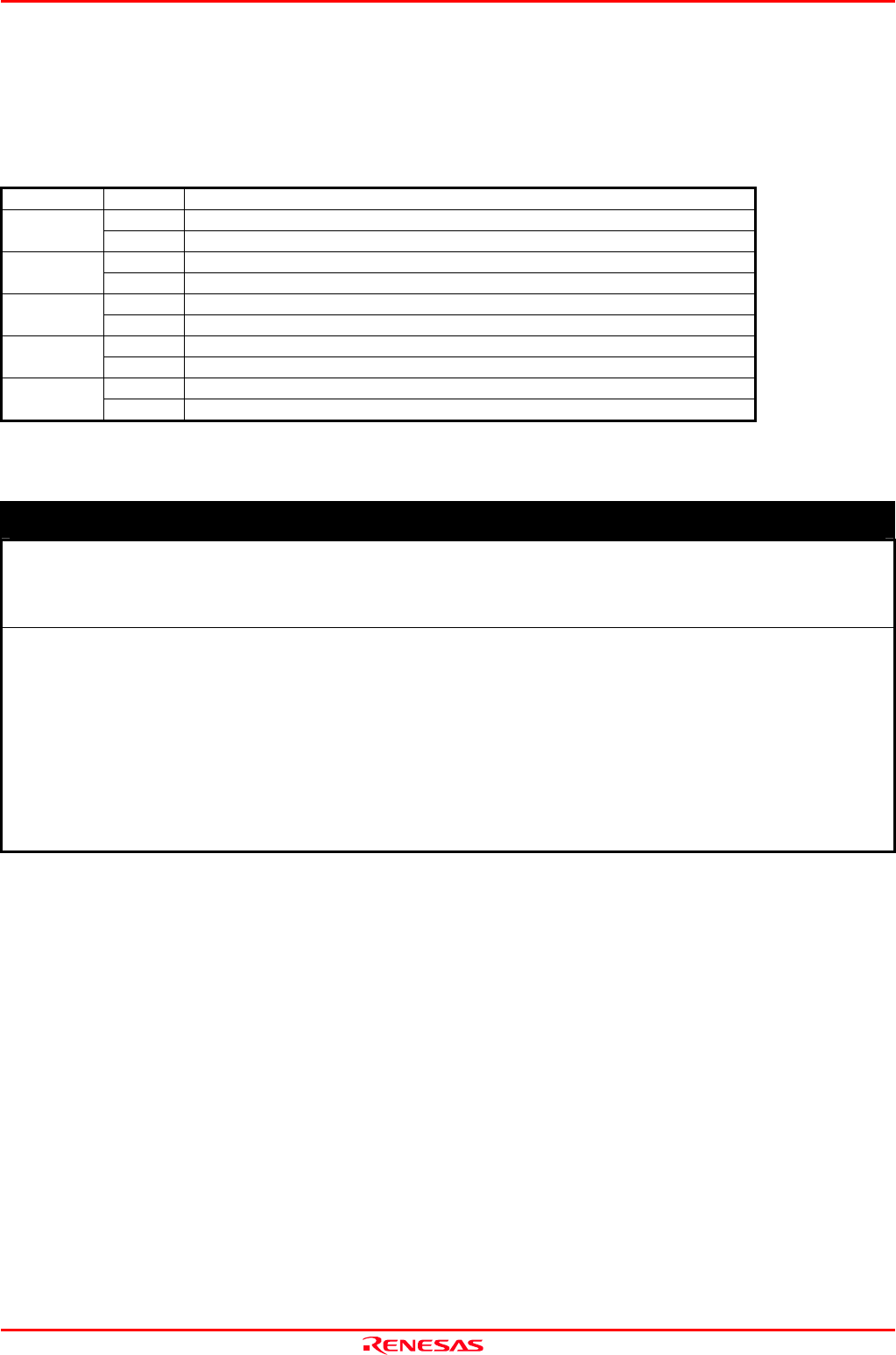
Table 1.4 Definitions of the target status LEDs
Name Status Meaning
ON Power is supplied to the user system.
POWER
OFF Power is not supplied to the user system.
ON Target MCU clock is supplied.
CLOCK
OFF Target MCU clock is not supplied.
ON Target MCU is being reset, or reset signal of the user system is held low.
RESET
OFF Target MCU is not being reset.
ON User program is being executed.
RUN
OFF User program has been halted.
ON CPU clock of target MCU is not oscillating.
HALT
OFF CPU clock of target MCU is oscillating.
IMPORTANT
Note on the Target Status POWER LED:
z If the MCU has two or more Vcc terminals, the LED does not light unless power is supplied to all the
terminals.
Notes on the Target Status CLOCK LED:
z CLOCK LED is turned off when both main and sub clocks are not oscillating. If either clock is oscillating,
the LED is turned on.
z If the LED is not turned on, check the following.
(1) After powering on the PC4701 (before starting up the emulator debugger):
Make sure that the oscillator circuit board in the emulation pod is properly installed and it is oscillating
normally.
(2) After the emulator debugger is started up (after the Init dialog box settings are completed):
Make sure that the oscillator selected in the Init dialog box is oscillating normally.