


plever
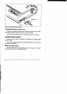
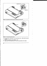
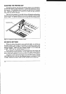
Figure
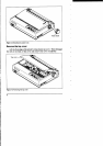
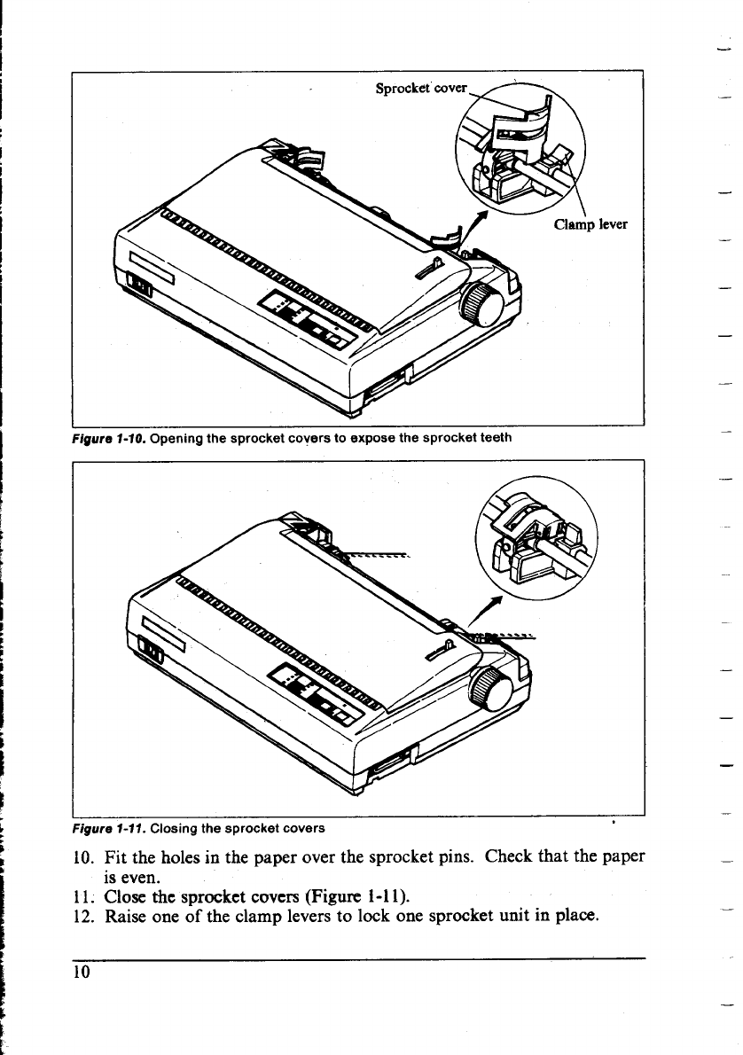
f-10. Opening the sprocket covers to expose the sprocket teeth
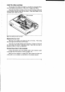
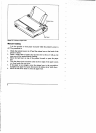
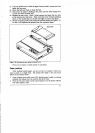
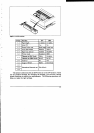
igure 1-11. Closing the sprocket covers
10. Fit the holesin the paper over the sprocket pins. Check that the paper
is even.
11. Close the sprocket covers (Figure i-n).
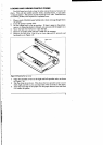
12. Raise one of the clamp levers to lock one sprocket unit in place.
10
—
.
—
—
—
—
—
—
—
—
—
—
—
—