9-2 Ultra Enterprise 6000/5000/4000 Systems Manual—November 1996
9
5. Turn the keyswitch to the diagnostic position ( ).
The system will turn on. The diagnostic position puts POST in interactive
mode and enables extensive POST tests.
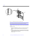
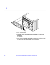
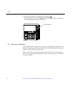
Figure 9-1 TTY Serial Port A
9.2 Hardware Indicators
Use the LEDs on the system front panel or the clock board to determine if the
system is operating normally. Use the LEDs on individual boards and power
supplies to locate specific malfunctions.
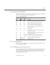
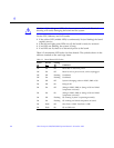
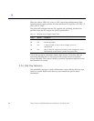
Many of the LED codes listed in Table 9-1 are common to the system front
panel and various types of boards. See Table 9-2 for exceptions for LED codes
for system boards.
TTY Serial Port A


