


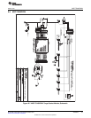
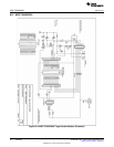
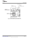
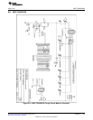
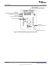
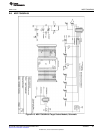
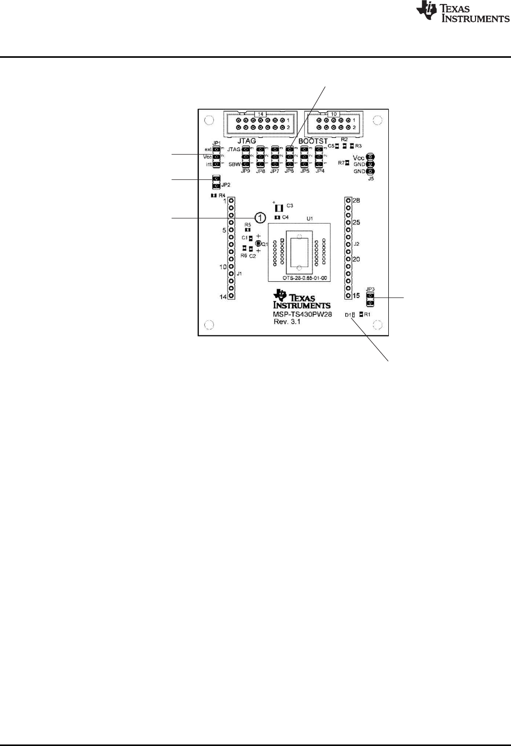
Jumper JP2
Open to measure current
Jumper JP3
Open to disconnect LED
LED D1 connected to P5.1
Jumper JP1
1-2 (int): Power supply via JTAG interface
2-3 (ext): External Power Supply
Jumper JP4 to JP9:
Close 1-2 to debug in Spy-Bi-Wire mode
Close 2-3 to debug in 4-wire JTAG mode
Orient Pin 1 of Device
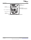
MSP-TS430PW28
www.ti.com
Figure B-12. MSP-TS430PW28 Target Socket Module, PCB
50
Hardware SLAU278F–May 2009–Revised December 2010
Submit Documentation Feedback
© 2009–2010, Texas Instruments Incorporated