


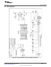
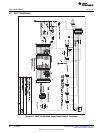
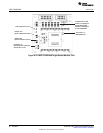
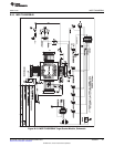
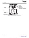
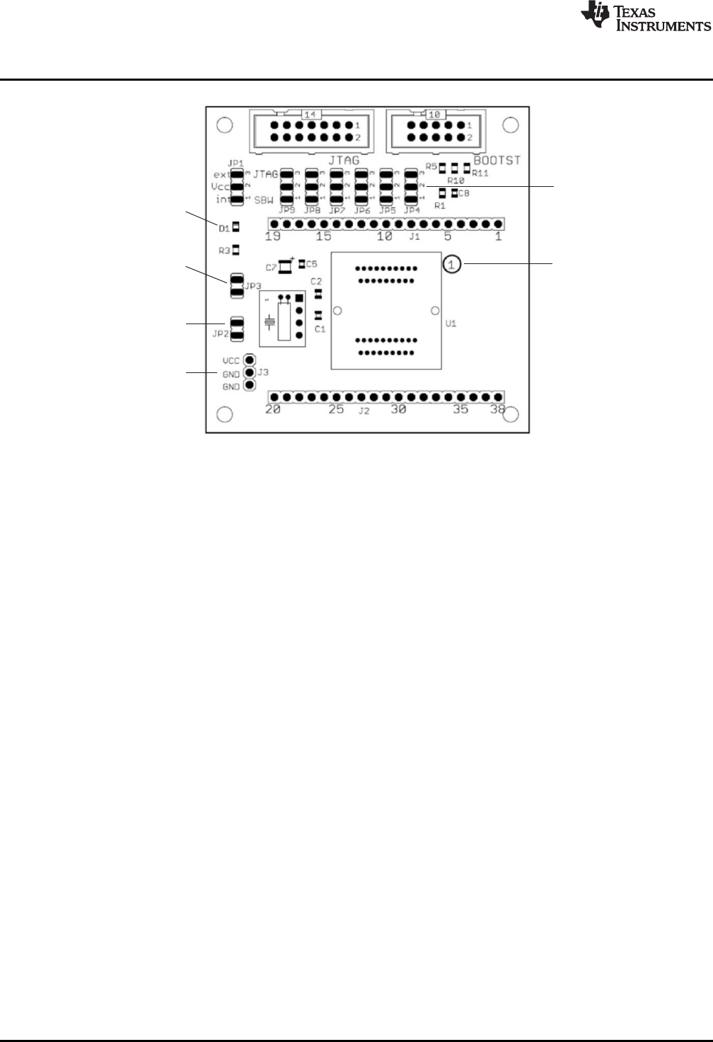
Orient pin 1 of
MSP430 device
LED connected to P1.0
Connector J3
External power connector
Jumper JP1 to 'ext'
Jumper JP3
Open to disconnect LED
Jumper JP2
Open to measure current
Jumpers JP4 to JP9
Close 1-2 to debug in
Spy-Bi-Wire Mode,
Close 2-3 to debug in
4-wire JTAG Mode
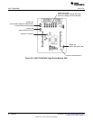
MSP-TS430DA38
www.ti.com
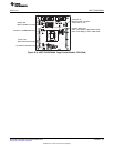
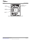
Figure B-16. MSP-TS430DA38 Target Socket Module, PCB
56
Hardware SLAU278F–May 2009–Revised December 2010
Submit Documentation Feedback
© 2009–2010, Texas Instruments Incorporated