


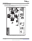
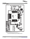
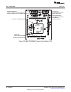
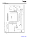
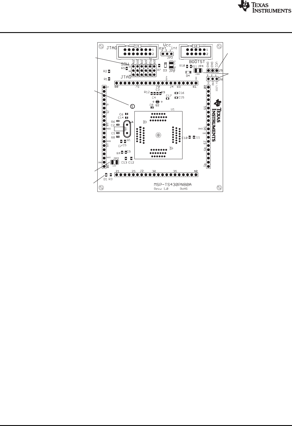
Connector J5
External power connector
Jumper JP3 to "ext"
Orient Pin 1 of MSP430 device
Jumpers JP5 to JP10
Close 1-2 to debug in Spy-Bi-Wire mode
Close 2-3 to debug in 4-wire JTAG mode
D1 LED connected to P1.0
Jumper JP2
Open to disconnect LED
If the system should
be supplied via LDOI (J6),
close JP4 and
set JP3 to external
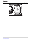
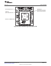
MSP-TS430PN80A
www.ti.com
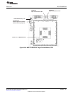
Figure B-38. MSP-TS430PN80A Target Socket Module, PCB
90
Hardware SLAU278F–May 2009–Revised December 2010
Submit Documentation Feedback
© 2009–2010, Texas Instruments Incorporated