www.ti.com
MSP-TS430PN80USB
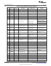
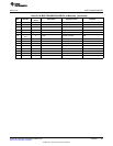
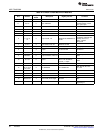
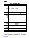
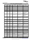
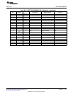
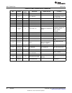
Table B-20. MSP-TS430PN80A Bill of Materials
No. per
Position Ref Des Description DigiKey Part No. Comment
Board
1 C1, C2 0 12pF, SMD0805 DNP
2 C3, C4 0 47pF, SMD0805 DNP
C6, C7,
3 3 10uF/6.3V, SMD0805 DNP C10
C10, C12
C5, C11,
4 C13, C14, 5 100nF, SMD0805 311-1245-2-ND
C15
5 C8 1 2.2nF, SMD0805
6 C9 1 470nF, SMD0805 478-1403-2-ND
7 C16 1 4.7uF, SMD0805
8 C17 1 220nF, SMD0805
9 D1 1 green LED, SMD0805 P516TR-ND
SAM1029-20-ND
DNP: Headers and receptacles
J1, J2, J3, (Header)
10 0 20-pin header, TH enclosed with kit. Keep vias free of
J4 SAM1213-20-ND
solder:
(Receptacle)
11 J5 , J6 2 3-pin header, male, TH
JP3, JP5,
place jumpers on pins 2-3 on JP5,
JP6, JP7,
12 7 3-pin header, male, TH SAM1035-03-ND JP6, JP7, JP8, JP9, JP10 place
JP8, JP9,
jumpers on pins 1-2 on JP3,
JP10
JP1, JP2,
13 3 2-pin header, male, TH SAM1035-02-ND Place jumper on header
JP4
14 10 Jumper 15-38-1024-ND See Pos. 12 and Pos. 13
14-pin connector, male,
15 JTAG 1 HRP14H-ND
TH
10-pin connector, male,
16 BOOTST 0 "DNP Keep vias free of solder"
TH
Micro Crystal MS3V-T1R
17 Q1 0 Crystal 32.768kHz, C(Load) = DNP: Q1 Keep vias free of solder
12.5pF
Q2: 4MHz Buerklin:
18 Q2 0 Crystal DNP: Q2 Keep vias free of solder
78D134
http://www.ettinger.de/Ar
Insulating
19 0 Insulating disk to Q2 t_Detail.cfm?ART_ART
disk to Q2
NUM=70.08.121
20 D3,D4 2 LL103A Buerklin: 24S3406
21 R3, R7 2 330 Ω, SMD0805 541-330ATR-ND
R1, R2,
R4, R6,
22 R8, 3 0 Ohm, SMD0805 541-000ATR-ND DNP: R6, R8, R9, R10, R11,R12
R9,R10,
R11, R12
23 R5 1 47k Ω, SMD0805 541-47000ATR-ND
24 U1 1 Socket:IC201-0804-014 Manuf.: Yamaichi
25 PCB 1 77 x 91 mm 2 layers
Adhesive about 6mm width, 2mm e.g., 3M Bumpons Part
26 4 Apply to corners at bottom side
plastic feet height No. SJ-5302
27 MSP430 2 MSP430F5329IPN DNP: enclosed with kit, supplied by TI
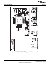
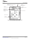
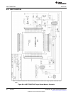
B.20 MSP-TS430PN80USB
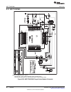
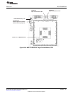
Due to the use of diodes in the power chain, the voltage on the MSP430F5xx device is approximately
0.3 V lower than is set by the debugging tool. Set the voltage in the IDE to 0.3 V higher than desired; for
example, to run the MCU at 3.0 V, set it to 3.3 V.
91
SLAU278F–May 2009–Revised December 2010 Hardware
Submit Documentation Feedback
© 2009–2010, Texas Instruments Incorporated


