June 2005 © TOSHIBA TEC e-STUDIO281c/351c/451c ADJUSTMENT
3 - 63
3
3.12 Adjustment of the RADF (MR-3018)
3.12.1 Adjustment of RADF Position
Perform this adjustment when the RADF is not installed in the correct position.
Note: Note:
Check if the image adjustment for the equipment is performed properly before this adjustment of
the RADF.
[A] Checking
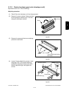
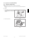
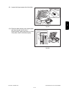
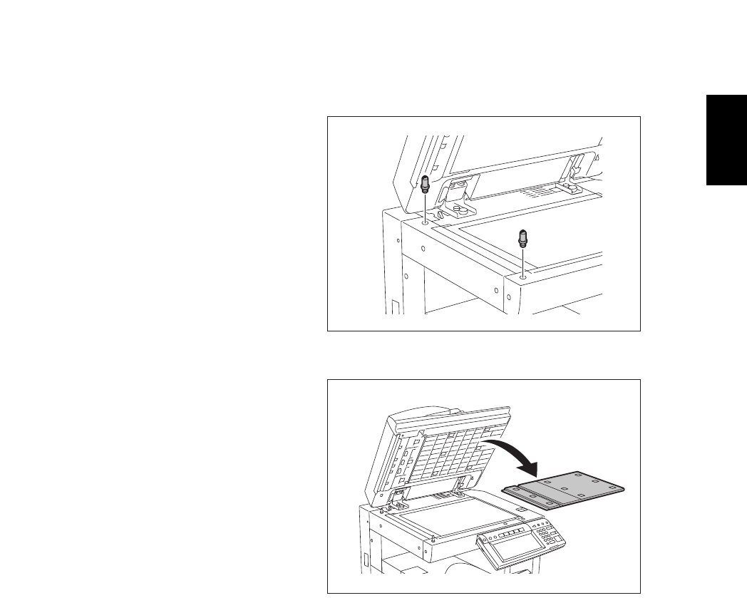
(1) Open the RADF and install 2 positioning pins
(the positioning pins are installed to the back
side of the hinge which is on the left side of
the RADF).
Fig.3-36
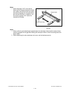
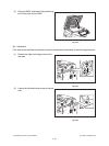
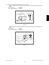
(2) Remove the platen sheet.
Fig.3-37


