e-STUDIO281c/351c/451c TROUBLESHOOTING June 2005 © TOSHIBA TEC
5 - 96
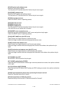
* If the desired image has not been obtained with the above measures or the more qualified image is
needed, adjustment the "deviation amount" in the adjustment mode (05). (Refer to 3.5.2 Color devi-
ation adjustment)
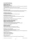
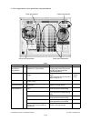
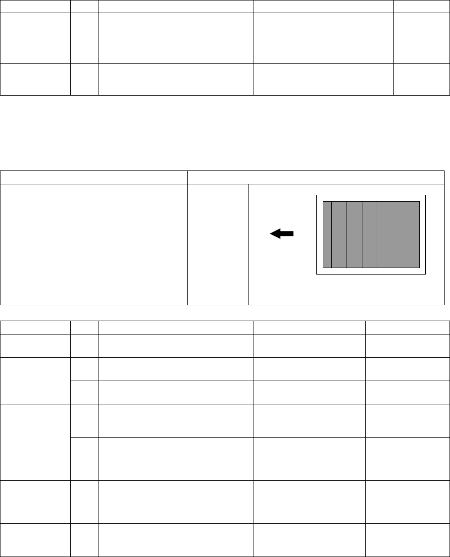
2) Uneven pitch and jitter image
<Symptoms>
Laser optical
unit
15 Check the grid pattern. Are the lines
of the primary scanning direction
warped?
Replace the laser optical unit. Fθ lens
characteris-
tic defect or
reflection
mirror warp
High-voltage
transformer
16 Check the connection of the high-
voltage supply terminal of the 1st or
2nd transfer rollers.
Correct or replace the terminal if
it is loosened or damaged.
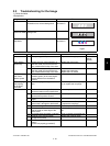
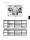
Original mode Location Phenomena
All modes Occurs cyclically at right
angles to paper feeding
direction
Uneven pitch
Fig.5-2
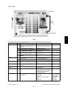
Cause/Section Step Check Item Measure Remark
1 Test printing (A3/LD) Output the built-in halftone
and grid patterns.
For the following
checks
Drum 2 Are there uneven pitches approx.
283 mm?
Replace the main motor.
3 Is there any damage on the drum
surface?
Clean or replace the
drum.
Drum rotation
abnormality
4 Check the main motor operation in
the test mode (03) to see if there is
any rotation abnormality of the drum.
Replace the main motor.
5 Check the main motor operation in
the test mode (03) to see if there is
any rotation abnormality of the drum.
Reconnect the connec-
tors.
Replace the harnesses.
Replace the LGC board.
Inadequate
main motor
rotation speed
6 Check the value set for main motor
rotation speed. (Is the value signifi-
cantly different from the default
value?)
Reset main motor speed
to 128.
Drum coupling 7 Loose coupling, damage, deforma-
tion
Tighten the screws if they
loosen. Or replace the
couplings.
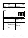
Cause/Section Step Check Item Measure Remark
Feeding
direction


