Appendices
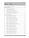
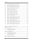
C.21 PJ1004 USB baord interface connector (6-pin) .................................................C-20
C.22 PJ4900 Bluetooth interface connector (20-pin) .................................................C-21
C.23 PJ1100 Sound board interface connector (30-pin).............................................C-21
C.24 PJ651 IEEE1394 interface connector (4-pin).....................................................C-22
C.25 PJ4500 LAN interface connector (14-pin).........................................................C-22
C.26 PJ8800 DC-IN connector (4-pin).......................................................................C-22
C.27 PJ8810 1st Battery connector (10-pin)...............................................................C-22
C.28 PJ1005 RTC Battery connector (2-pin)..............................................................C-23
C.29 PJ8770 FAN interface connector (3-pin) ...........................................................C-23
C.30 PJ5500 LCD interface connector (41-pin) .........................................................C-23
C.31 PJ5523 CRT interface connector (15-pin) .........................................................C-24
C.32 PJ5501 TV connector (4-pin).............................................................................C-24
C.33 PJ3000 System board interface connector (30-pin) ...........................................C-25
C.34 PJ3001 Internal Microphone connector (2-pin) .................................................C-25
C.35 PJ3002 External Microphone connector (6-pin)................................................C-25
C.36 PJ3003 Headphone connector (6-pin)................................................................C-26
C.37 PJ3100 System board interface connector (14-pin) ...........................................C-27
C.38 PJ3200 System board interface connector (10-pin) ...........................................C-28
C.39 PJ3300 System board interface connector (6-pin) .............................................C-29
C.40 PJ3301 USB port 2 interface connector (4-pin).................................................C-29
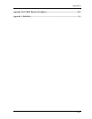
Appendix D Keyboard Scan/Character Codes................................................................ D-1
Appendix E Key Layout .....................................................................................................E-1
E.1 United Kingdom (UK) Keyboard...........................................................................E-1
E.2 United States (US) Keyboard.................................................................................E-1
Appendix F Wiring Diagrams ...........................................................................................F-1
F.1 Parallel Port Wraparound Connector .....................................................................F-1
F.2 Serial Port Wraparound Connector ........................................................................F-1
F.3 LAN Loopback Connector.....................................................................................F-2
Appendix G BIOS Rewrite Procedures ...........................................................................G-1
App-iv


