


Prestige 202H User’s Guide
Hardware Installation 2-1
Chapter 2
Hardware Installation
This chapter shows you how to make the cable connections to your router.
2.1 Front Panel
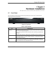
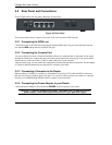
The LED indicators on the front panel indicate the operational status of the router. The table after the
diagram describes the LED functions:
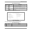
Figure 2-1 Front Panel
Table 2-1 LED Functions
LED DESCRIPTION
PWR/SYS The PWR/SYS (power/system) LED turns steady on green when power is applied to
the router and it has boot up properly.
A green blinking PWR/SYS LED indicates the router is performing a system test or
rebooting.
When the router senses low voltage power, the PWR/SYS LED turns steady on red.
LAN 1-4 A steady green light indicates a successful 10Mbs Ethernet connection, while an
orange light indicates a successful 100Mbs connection. The LEDs will blink when
data is being sent/received.
ISDN LNK, B1, B2 The LNK LED is on when the router is connected to an ISDN switch and the line
has been successfully initialized. The B1 (B2) LED remains steady on when data is
being sent/received on the B1 (B2) bearer channel.